Unreeling apparatus and method

Active Publication Date: 2020-10-01
SMS GRP GMBH
View PDF0 Cites 0 Cited by
  • Summary
  • Abstract
  • Description
  • Claims
  • Application Information

AI Technical Summary

Benefits of technology

[0003]It is the task of the present invention to increase operational safe

Problems solved by technology

In this regard, it is apparent that the unreeling apparatuses and methods presented in this document can be s

Method used


Image

  • Unreeling apparatus and method
  • Unreeling apparatus and method
  • Unreeling apparatus and method

Examples


Embodiment Construction

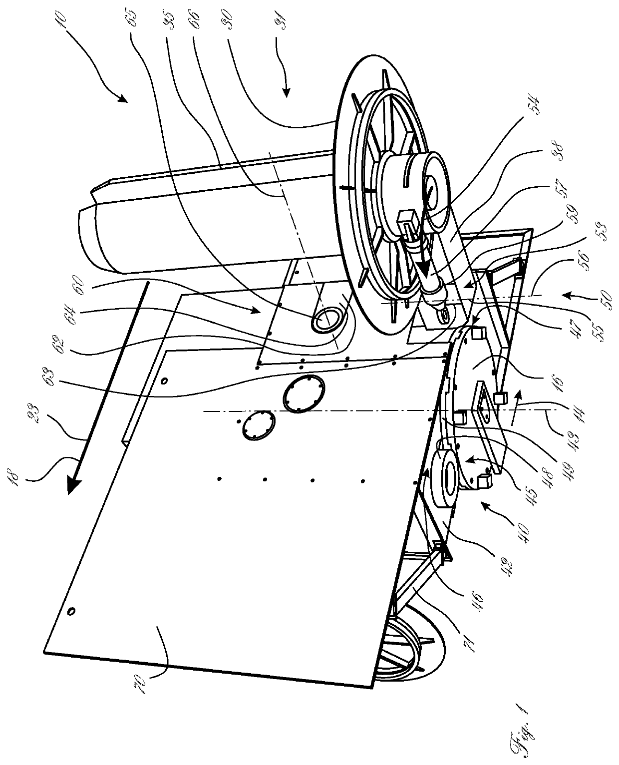
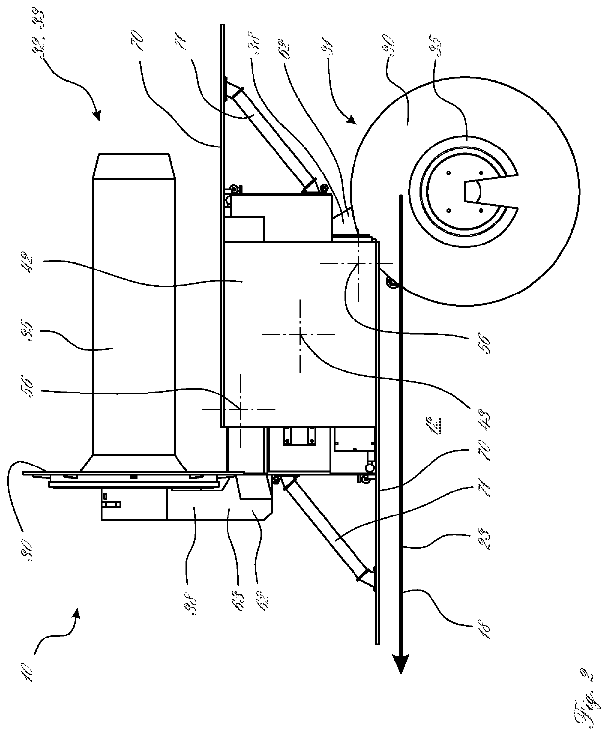
[0042]FIGS. 1 and 2 show an unreeling apparatus 10, in which two reel mandrels 35 are each disposed on a mandrel crown 30, wherein one of the two reel mandrels 35 is situated in the pull-off position 31 and the second of the two reel mandrels 35 is situated in the preparation position or loading position 32, 33, wherein the second of the two reel mandrels 35 cannot be seen in the representation according to FIG. 1.

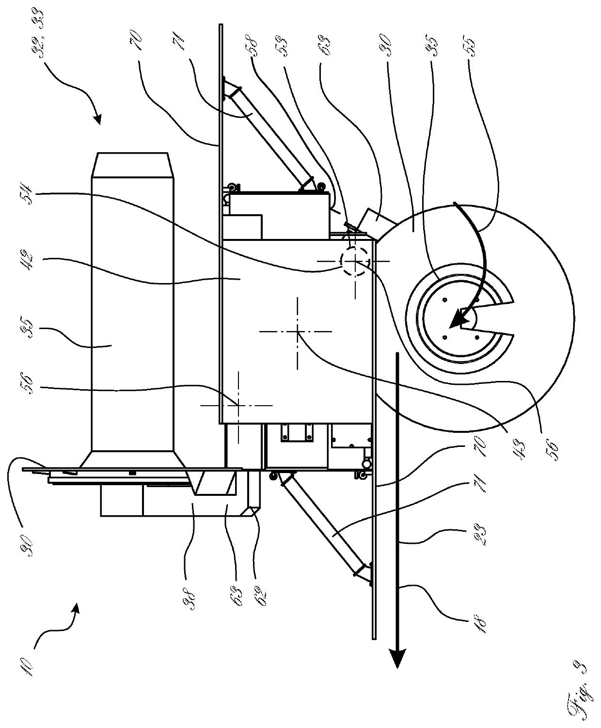
[0043]The unreeling apparatus 10 can allow a wire 22 to be pulled off in the pull-off direction 23, in known manner, when the wire 22, which is situated on the reel crown 30 as a ring 20, is put under stress from a pull 18. The wire 22 and the ring 20 are not shown in FIGS. 1 to 3, but they are represented schematically in FIGS. 4 to 7.

[0044]The unreeling apparatus 10 comprises a rotary body 42, which is mounted on the floor 12 so as to be displaceable about a rotation axis 43.

[0045]A displacement device 40 serves for displacing the reel mandrels 35 between a pull-off posi...


PUM

PropertyMeasurementUnit
Heightaaaaaaaaaa

Abstract

In order to increase the operational safety of an unreeling apparatus and an unreeling method at high working speed, an unreeling apparatus for unreeling a ring of wire along a pull-off direction, having at least two reel crowns, which can each be brought into a pull-off position and into a preparation position and/or loading position by way of a displacement device, includes a safety apparatus having an overload safety device and having a safety guide track, which has a directional component that faces in the pull-off direction and acts independently of the other reel crown, at least for the reel crown situated in the pull-off position, wherein the overload safety device holds the reel crown situated in the pull-off position in the pull-off position and, in the event of an overload, releases the reel crown situated in the pull-off position into the safety guide track.

Description

BACKGROUND OF THE INVENTION1. Field of the Invention[0001]The invention relates to an unreeling apparatus and to an unreeling method.2. Description of the Related Art[0002]It is known, for example from DE 87 04 357 U1, to unreel wires, in particular metallic wires, from reels, also called rings or coils, in that a pull is exerted on the wire. In this regard, it is apparent that the unreeling apparatuses and methods presented in this document can be suitable only for very small and easily bendable wires, since the design implementation is relatively delicate.SUMMARY OF THE INVENTION[0003]It is the task of the present invention to increase operational safety in an unreeling apparatus and an unreeling method at high working speed.[0004]The task of the invention is accomplished by means of unreeling apparatuses and unreeling methods having the characteristics of the independent claims. Further advantageous embodiments, if applicable also independent of these, are found in the dependent ...

Claims


Application Information

Patent Timeline
IPC IPC(8): B65H63/036B21C47/24B21C47/18B65H49/24B65H57/00
CPCB21C47/245B65H49/24B65H57/006B65H63/036B21C47/18B65H2701/30B21C47/242B65H49/32B65H63/04B65H67/02B65H67/048B65H2701/36B65H49/28
Inventor LINDBUECHL, JOERGCMIEL, THOMASHESSBERGER, DIRKGREUEL, HEINZ-WILLI
Owner SMS GRP GMBH
Why Eureka
Try Eureka