Multilayer piezoelectric element

a piezoelectric element and multi-layer technology, applied in the field of multi-layer piezoelectric elements, can solve the problems of insufficient crack generation, crack generation in the interface between the internal electrodes and the piezoelectric layers, etc., and achieve the effect of preventing crack generation

Inactive Publication Date: 2020-10-01
TDK CORPARATION
View PDF0 Cites 0 Cited by
  • Summary
  • Abstract
  • Description
  • Claims
  • Application Information

AI Technical Summary

Benefits of technology

[0005]The present invention has been achieved under such circumstances. It is an object of the in

Problems solved by technology

In the multilayer piezoelectric elements, cracks may be generated in an interface between the internal electrodes and the piezoelectric layers due to the stress generated in the laminated body.
However, the technique

Method used


Image

  • Multilayer piezoelectric element
  • Multilayer piezoelectric element
  • Multilayer piezoelectric element

Examples


first embodiment

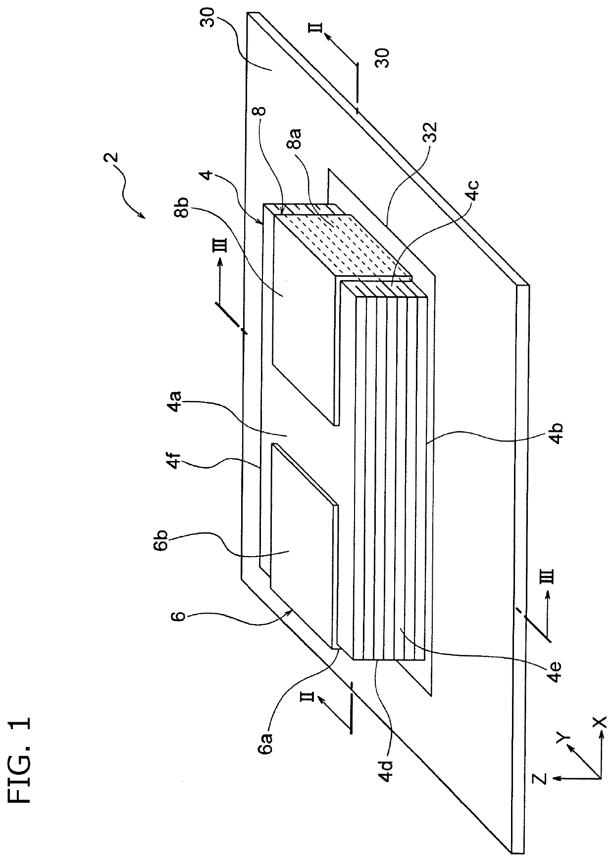
[0032]FIG. 1 is a schematic perspective view of a vibration device according to the present embodiment. As shown in FIG. 1, a multilayer piezoelectric element 2 is bonded on a vibration plate 30 via an adhesive layer 32. The multilayer piezoelectric element 2 is formed from a laminated body 4, a first external electrode 6, and a second external electrode 8.

[0033]The laminated body 4 has a substantially rectangular parallelepiped shape and has a front surface 4a and a back surface 4b substantially perpendicular to the Z-axis direction, lateral surfaces 4c and 4d substantially perpendicular to the X-axis (first axis) direction, and lateral surfaces 4e and 4f substantially perpendicular to the Y-axis (second axis) direction. Incidentally, insulating protect layers (not illustrated) may be formed on the lateral surfaces 4c-4f of the laminated body 4 excluding areas on which the external electrodes 6 and 8 are formed. In the figures, the X-axis, the Y-axis, and the Z-axis are substantial...

second embodiment

[0087]Hereinafter, Second Embodiment of the present invention is explained FIG. 3B, FIG. 4B, and FIG. 7B. Incidentally, the common features between First Embodiment and Second Embodiment are not explained and are provided with the same references.

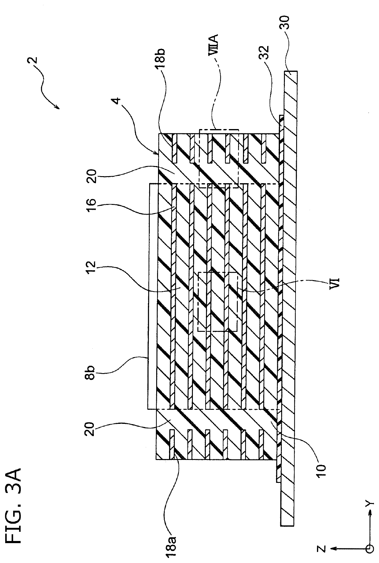
[0088]FIG. 3B is a schematic view of a Y-Z cross section of a multilayer piezoelectric element 3 according to Second Embodiment. FIG. 4B is a plane view of an electrode pattern 24b of the multilayer piezoelectric element 3. In the multilayer piezoelectric element 3, unlike First Embodiment, no dummy electrode layer 18 is formed in the outer circumference of the internal electrode layer 16 as shown in FIG. 3B and FIG. 4B. Thus, only the piezoelectric layer 10 is laminated in the outer circumferential part 14 of the internal electrode layer 16.

[0089]In such a multilayer structure, the size of the internal electrode layer 16 (W1×W2) is preferably about 0.90 times to 0.98 times larger than the size of the piezoelectric layer (Wx×Wy). In such a ...

examples

[0096]Hereinafter, the present invention is explained based on further detailed examples, but is not limited thereto.


PUM


Abstract

A multilayer piezoelectric element includes a laminated body and a lateral electrode. The laminated body includes a piezoelectric layer and an internal electrode layer. The piezoelectric layer is formed along a plane including a first axis and a second axis perpendicular to each other. The internal electrode layer is laminated on the piezoelectric layer. The internal electrode layer has a leading portion exposed to the lateral surface of the laminated body and is electrically connected with the lateral electrode via the leading portion. Ro is higher than Rc in the the laminated body. Ro is an existence rate of outer circumferential pores existing in the piezoelectric layer located in an outer circumferential part of the internal electrode layer. Rc is an existence rate of central pores existing in a central part of the laminated body.

Description

BACKGROUND OF THE INVENTION[0001]The present invention relates to a multilayer piezoelectric element.[0002]Multilayer piezoelectric elements have a structure in which internal electrodes and piezoelectric layers are laminated and can increase displacement amount and driving force per unit volume compared to non-multilayer piezoelectric elements. In the multilayer piezoelectric elements, cracks may be generated in an interface between the internal electrodes and the piezoelectric layers due to the stress generated in the laminated body. The generation of cracks in the laminated body deteriorates characteristics (e.g., displacement amount) of the piezoelectric element. Thus, a technique of preventing the generation of cracks is required.[0003]For example, Patent Document 1 discloses a technique of preventing the generation of cracks in the piezoelectric layers during manufacture by forming a dummy electrode around the internal electrode layer. However, the technique disclosed by Paten...

Claims


Application Information

Patent Timeline
IPC IPC(8): H01L41/083H01L41/047H01L41/273
CPCH01L41/273H01L41/0838H01L41/0471H10N30/871H10N30/872H10N30/877H10N30/875H10N30/508H10N30/053
Inventor ISHIZAKI, MAKOTOHIRAKAWA, MASAHARU
Owner TDK CORPARATION
Why Eureka
Try Eureka