Butterfly Valve

a butterfly valve and valve body technology, applied in the field of butterfly valves, can solve the problems of corrosion and the butterfly valve no longer meeting the requirements, and achieve the effect of simple assembly and medium-resistan

Active Publication Date: 2020-10-15
GEORG FISCHER ROHRLEITUNGSSYST
View PDF0 Cites 0 Cited by
  • Summary
  • Abstract
  • Description
  • Claims
  • Application Information

AI Technical Summary

Benefits of technology

[0008]It is an aspect of the invention to propose a butterfly valve and a production method therefor, with the butterfly valve be

Problems solved by technology

It is disadvantageous here that the butterfly valve has a high weight and that, upon detachment o

Method used


Image

  • Butterfly Valve
  • Butterfly Valve
  • Butterfly Valve

Examples


Embodiment Construction

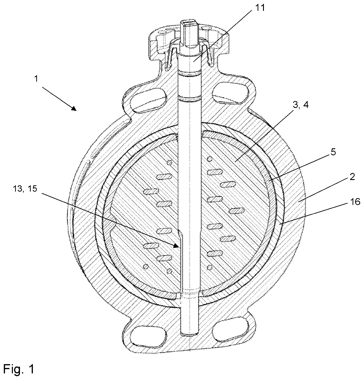
[0028]The drawing illustrated in FIG. 1 shows a longitudinal section through a butterfly valve 1 according to the invention. The butterfly valve 1 is used to shut off and regulate a medium which flows through a pipeline. The butterfly valve 1 comprises a housing 2, wherein the housing 2 is configured in one piece. This has the advantage that additional seals are omitted, and also that a butterfly valve 1 can be assembled simply and economically. The housing 2 is preferably formed from plastic, with other materials, such as metal or composite materials, being also conceivable. In order to seal the butterfly valve 1 in an optimal manner, a seal 16 is arranged in the housing 2. In order to block or regulate the throughflow of the medium, the butterfly valve 1 comprises a disc 3. The disc 3 can be pivoted along the shaft 11. The embodiment depicted shows a centric butterfly valve 1, with eccentric embodiments in which the shaft does not extend through the centre of the disc in relation ...


PUM

PropertyMeasurementUnit
Electrical resistanceaaaaaaaaaa

Abstract

Butterfly valve for shutting off or regulating a medium, which flows through a pipeline, containing a housing, wherein the housing is configured in one piece and is preferably composed of plastic, a disc and a shaft, wherein the disc can be pivoted along the shaft between an open position and a closed position, wherein the disc comprises a core composed of plastic and a shell composed of plastic, wherein the plastic of the core and the plastic of the shell are different.

Description

CROSS-REFERENCE TO RELATED APPLICATIONS[0001]The present application is based on, and claims priority from European Patent Application No. 19 168 297.0, filed Apr. 10, 2019, the disclosure of which is hereby incorporated by reference herein in its entirety.FIELD OF THE INVENTION[0002]The invention relates to a butterfly valve for shutting off or regulating a medium, which flows through a pipeline, containing a housing, wherein the housing is configured in one piece and is preferably composed of plastic, a disc and a shaft, wherein the disc can be pivoted along the shaft between an open position and a closed position.BACKGROUND OF THE INVENTION[0003]In pipeline construction, butterfly valves are used to close pipelines which transport liquid or gaseous media or to regulate the throughflow. To this end, it is necessary for the valves to withstand the pressure in the pipelines.[0004]JP 6387493 B2 discloses a butterfly valve in which the valve comprises metal plates inside in order to a...

Claims


Application Information

Patent Timeline
IPC IPC(8): F16K1/22F16K27/02
CPCF16K1/222F16K27/0218F16K1/36F16K1/32B29C45/14819F16K25/005
Inventor JAECKLE, TIMOBUERGI, STEFAN
Owner GEORG FISCHER ROHRLEITUNGSSYST
Why Eureka
Try Eureka