Supercharge Your Innovation With Domain-Expert AI Agents!

Pivot joint system and rear view device therewith

a rear view device and pivot joint technology, applied in the direction of superstructure connections, optical viewing, superstructure connections, etc., can solve problems such as rear view device damage, and achieve the effect of simple and inexpensive manufactur

Active Publication Date: 2020-10-22
SMR PATENTS S A R L
View PDF0 Cites 0 Cited by
  • Summary
  • Abstract
  • Description
  • Claims
  • Application Information

AI Technical Summary

Benefits of technology

The spring mechanism in this invention uses a special spring with two tails to securely lock into the base frame and case frame components. This allows the spring to act under torsion when the head is broken out. The torsional load applied to the spring forces the head back to its original position. The compression of the spring when lifting the case frame component also helps to bring back the head's self-return function. The components of this mechanism can be easily manufactured from inexpensive polymeric materials.

Problems solved by technology

Manually forcing the head back from the knocked out position into in particular the driving position is time consuming and might cause damage of the rear view device.

Method used


Image

  • Pivot joint system and rear view device therewith
  • Pivot joint system and rear view device therewith
  • Pivot joint system and rear view device therewith

Examples


first embodiment

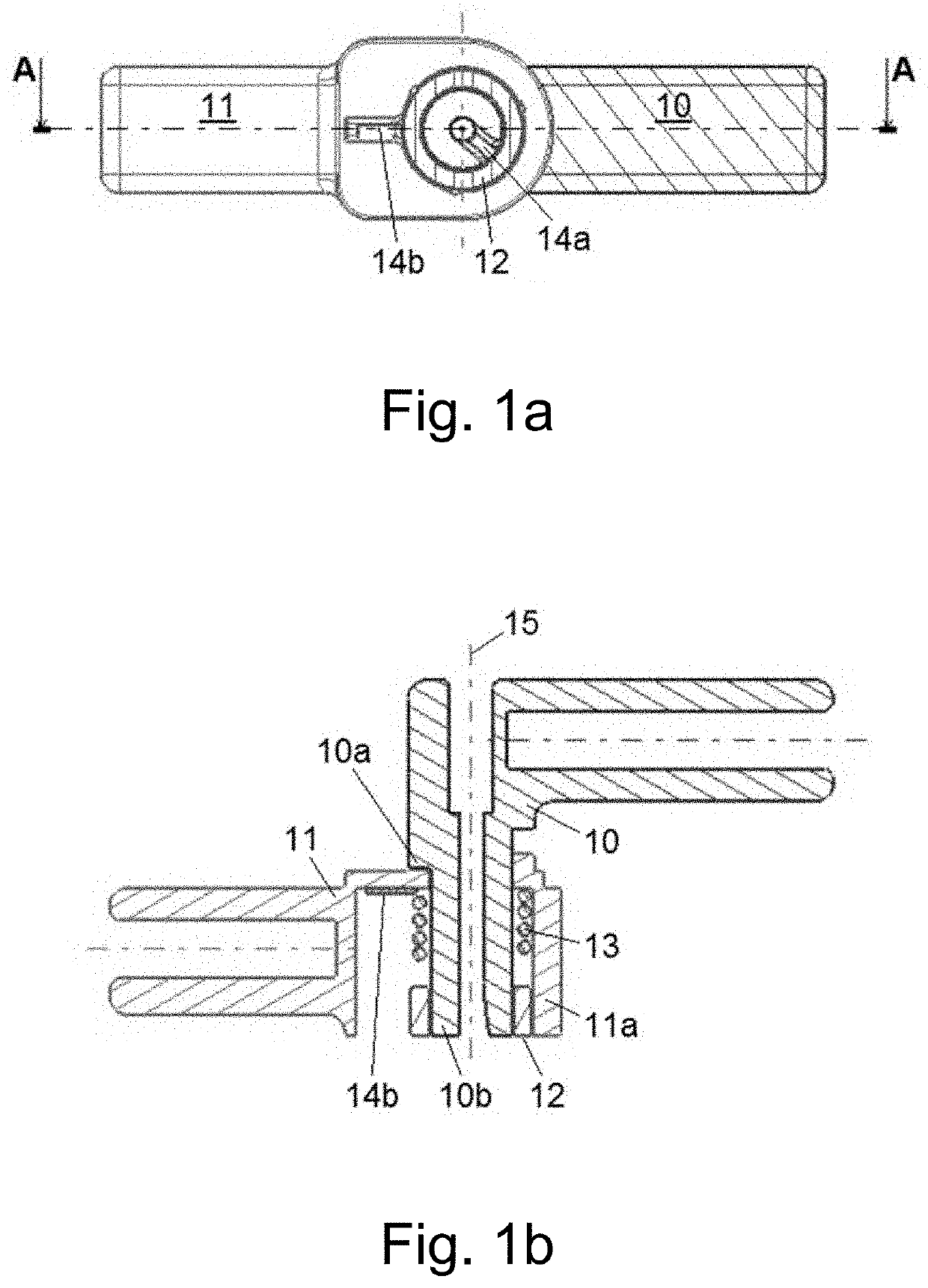
[0047]In the invention shown in FIGS. 1a and 1b, the pivot joint system comprises a case frame 10 belonging to or being provided by the head 60 of a rear view device, a base frame 11 belonging to or being provided by the base 50 of the rear view device, a spacer 12 between the case frame 10 and the base frame 11, and a torsion spring 13 attached via a first locking means 14a to the case frame 10 and via a second locking means 14b to the base frame 11. In other words, the torsion spring 13 is provided with two tails for the two locking means 14a, 14b.

[0048]The case frame 10 is provided with a step 10a against which a cylindrical section 11a of the base frame 11 acting as a spring case is resting. Below the step 10a the case frame 10 is provided with a cylindrical section 10b being arranged concentrically around a pivot axis 15. The spring 13 is arranged around at lease a part of the cylindrical section 10b. The spring case cylindrical section 11a is spaced from the cylindrical secti...

third embodiment

[0061]In the invention shown in FIGS. 4 to 9, the pivot joint system comprises a case frame 100, a base frame 110, a bayonet tower 120 and spring 130 as best seen in FIG. 4.

[0062]The case frame 100 is shown in more detail in FIG. 5 and is provided with three detents 102 each formed with a recess or step 101 at its inner side and a lip 102a around its outer periphery. The lips 102a ensure an interface with a not shown motor cradle of an articulation system, which is suited for moving a not shown reflective element and is attached to the base frame 100 in the assembled rear view device. Still further, the case frame 100 is provided with two head movement stop elements 103.

[0063]FIG. 6 shows further details of the base frame 110 in form of a cylindrical section 111 from which three detents 113 extend, with each detent 113 being provided with a recess 114.

[0064]FIG. 7a shows a sub assembly provided by the case frame 100 and the bayonet tower 120. In fact, those two parts are fixedly sec...


PUM


Abstract

A pivot joint system of a rear view device includes a base to be fixed to a vehicle and a head rotatable relative to the base, the pivot joint system acting between two components that rotate with respect to one another around an axis to control rotation from a first set position to at least one second set position, with each of the two components including a cylindrical section and a resilient means being arranged within a cylindrical space between said cylindrical sections to act between the two components.

Description

CROSS-REFERENCE TO RELATED APPLICATIONS[0001]This application is a National Stage Entry of International Patent Application No. PCT / EP2018 / 063665, filed Nov. 24, 2018, which claims the benefit of German Patent Application No. DE 10 2017 111 460.2, filed May 24, 2017, each of which is hereby incorporated by reference in its entirety for all purposes.BACKGROUND1. Field of the Invention[0002]The present disclosure relates to a pivot joint system of a rear view device. It also relates to a rear view device with a base to be fixed to a vehicle, a head rotatable relative to the base and said pivot joint system.2. Related Art[0003]US 2014 / 0268379 A1 refers to a method of moving a mirror, said method comprising the steps of providing an arm which supports a mirror at one end thereof; enabling said arm to move along a first axis or about a second axis at another end thereof, wherein said arm a) rotates about said axis in a first rotational direction or b) moves along said second axis in a fi...

Claims


Application Information

Patent Timeline
IPC IPC(8): B60R1/076F16C11/12
CPCB60R1/076B62D27/04F16C11/12
Inventor SCOTT-COLLINS, CALLUMLETTIS, ANDREW
Owner SMR PATENTS S A R L
Features
  • R&D
  • Intellectual Property
  • Life Sciences
  • Materials
  • Tech Scout
  • Unparalleled Data Quality
  • Higher Quality Content
  • 60% Fewer Hallucinations
Learn More