Waste liquid treating apparatus

Active Publication Date: 2020-10-29
DISCO CORP
View PDF0 Cites 0 Cited by
  • Summary
  • Abstract
  • Description
  • Claims
  • Application Information

AI Technical Summary

Benefits of technology

The present invention is about a waste liquid treating apparatus that can effectively sediment debris in a sedimentation tank. The invention includes a zigzag channel defined by boxes, which allows for easy removal of the sediment from the tank. This reduces the burden on workers who handle the waste water treating apparatus.

Problems solved by technology

However, it is difficult for the sedimentation tank with the vertically zigzag channel therein to allow the debris to settle effectively as a sediment because the liquid tends to fling up the sediment while flowing through the vertically zigzag channel.

Method used


Image

  • Waste liquid treating apparatus
  • Waste liquid treating apparatus
  • Waste liquid treating apparatus

Examples


first embodiment

1. First Embodiment

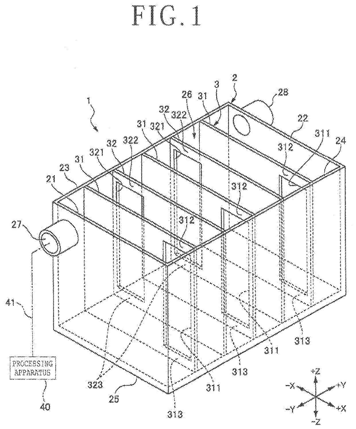
[0015]A waste liquid treating apparatus 1, illustrated in FIG. 1, according to a first embodiment of the present invention is an apparatus for receiving a processed waste liquid containing debris discharged from a processing apparatus 40 that processes a workpiece by supplying a processing fluid thereto, allowing the debris to settle, and removing the sedimented debris from the received waste liquid.

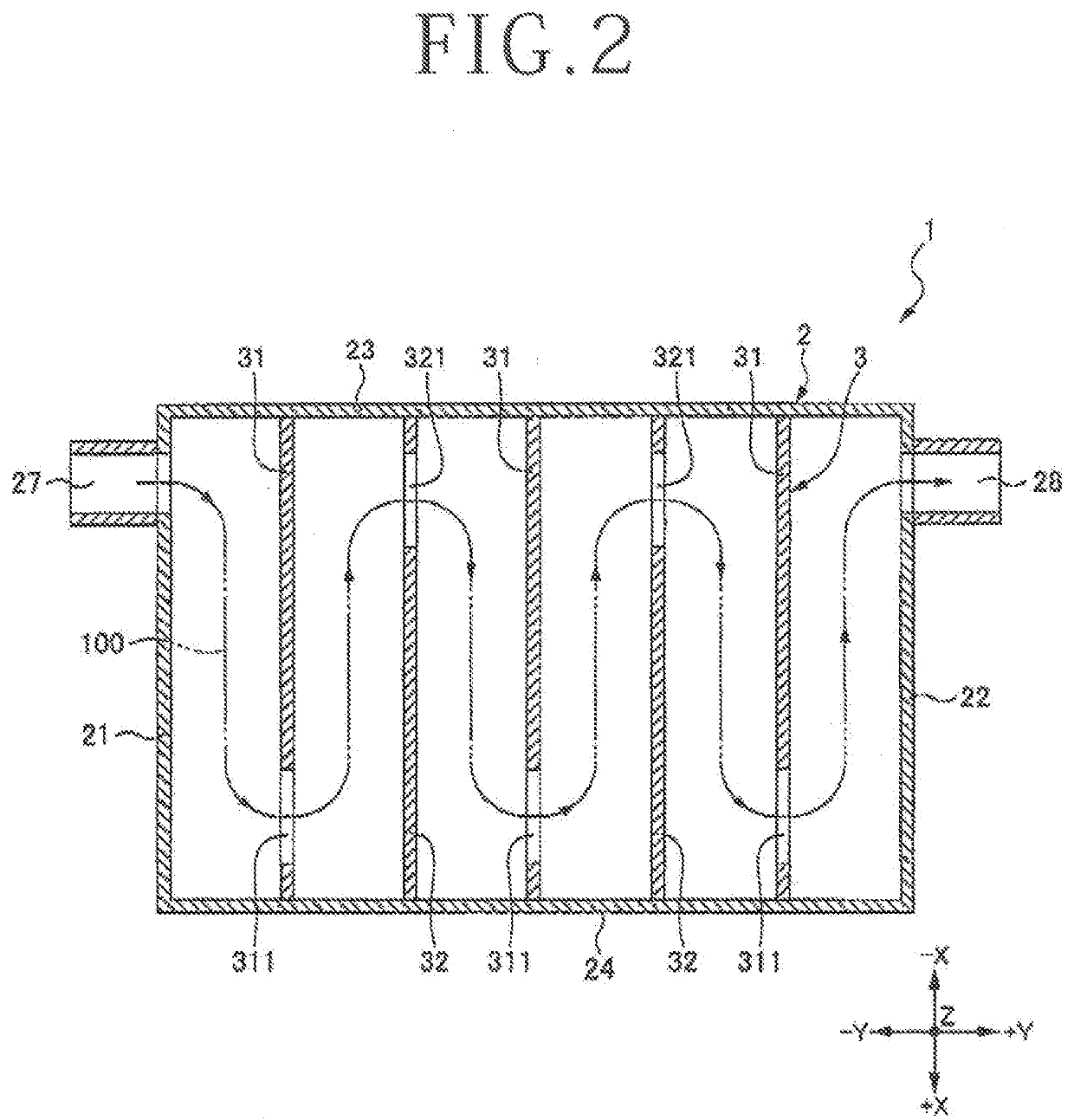
[0016]As illustrated in FIG. 1, the waste liquid treating apparatus 1 includes a sedimentation tank 2 that is of a box shape having four side plates 21, 22, 23, and 24 and a bottom plate 25 interconnecting the lower ends of the side plates 21, 22, 23, and 24, with an upper opening 26 being open opposite the bottom plate 25, an inlet 27 joined to the side plate 21 at an end of the sedimentation tank 2, for introducing a waste liquid into the sedimentation tank 2, an outlet 28 joined to the side plate 22 at the other end of the sedimentation tank 2 in confronting relatio...

second embodiment

2. Second Embodiment

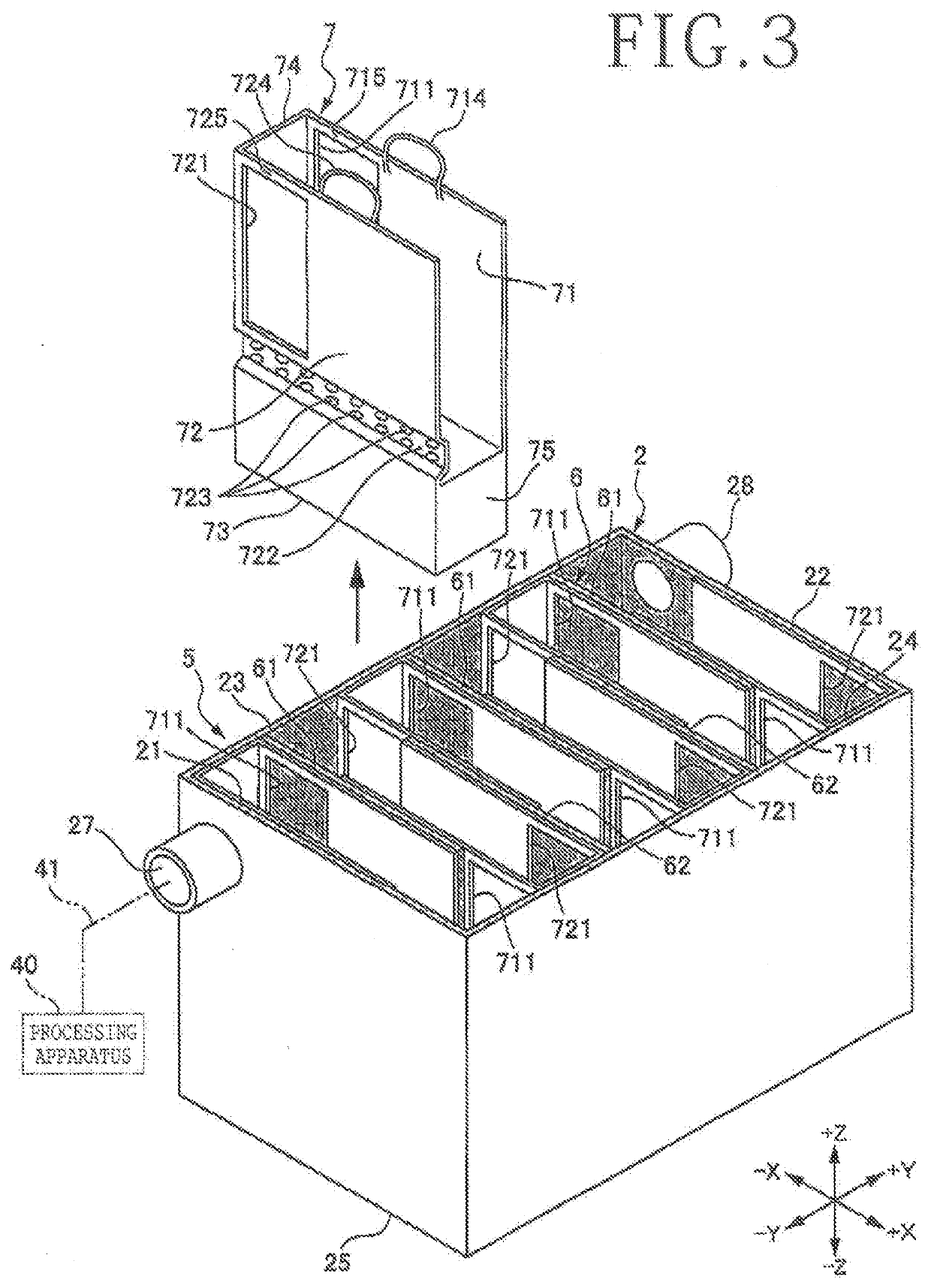
[0027]A waste liquid treating apparatus 5, illustrated in FIG. 3, according to a second embodiment of the present invention is an apparatus for receiving a waste liquid containing debris discharged from a processing apparatus 40 that processes a workpiece by supplying a processing fluid thereto, allowing the debris to settle, and removing the sedimented debris from the received waste liquid, as with the waste liquid treating apparatus 1 illustrated in FIG. 1.

[0028]As illustrated in FIG. 3, the waste liquid treating apparatus 5 includes a sedimentation tank 2 that is of a box shape having four side plates 21, 22, 23, and 24 and a bottom plate 25 interconnecting the lower ends of the side plates 21, 22, 23, and 24, with an upper opening 26 being open opposite the bottom plate 25, an inlet 27 joined to the side plate 21 at an end of the sedimentation tank 2, for introducing a waste liquid into the sedimentation tank 2, an outlet 28 joined to the side plate 22 at the...


PUM

PropertyMeasurementUnit
Timeaaaaaaaaaa

Abstract

A sedimenting assembly for sedimenting debris contained in a processed waste liquid in a sedimentation tank includes a plurality of partition plates extending vertically across a direction in which the processed waste liquid flows and disposed at spaced intervals in the direction, thereby defining a zigzag channel through which the processed waste liquid flows horizontally. The zigzag channel ensures a time during which to sediment the debris against a time during which the processed waste liquid flows through the zigzag channel, allowing the debris to settle reliably.

Description

BACKGROUND OF THE INVENTIONField of the Invention[0001]The present invention relates to a waste liquid treating apparatus for removing debris contained in a processed waste liquid discharged from a processing apparatus.Description of the Related Art[0002]As disclosed in JP 2004-230527A and JP 2011-235260A, for example, when unwanted debris is to be removed from a liquid, the liquid is guided to pass through a vertically zigzag channel in a sedimentation tank and hence to flow upwardly and downwardly repeatedly, thereby allowing the debris to settle as a sediment to be removed.SUMMARY OF THE INVENTION[0003]However, it is difficult for the sedimentation tank with the vertically zigzag channel therein to allow the debris to settle effectively as a sediment because the liquid tends to fling up the sediment while flowing through the vertically zigzag channel.[0004]It is therefore an object of the present invention to provide a waste liquid treating apparatus for sedimenting debris effect...

Claims


Application Information

Patent Timeline
IPC IPC(8): B01D21/00B01D21/02
CPCB01D21/0033B01D21/02B01D36/04B01D21/0003B01D21/0006B01D21/003B01D21/0012B01D21/0087Y02P70/10B01D21/2483C02F1/52B01D21/0066
Inventor SUWANO, JUNFURONAKA, TAKESHI
Owner DISCO CORP
Why Eureka
Try Eureka