Aerial vehicle safety apparatus and aerial vehicle
a safety apparatus and aerial vehicle technology, applied in the field of aerial vehicles, can solve problems such as the widespread use of interfered unmanned aircra
- Summary
- Abstract
- Description
- Claims
- Application Information
AI Technical Summary
Benefits of technology
Problems solved by technology
Method used
Image
Examples
first embodiment
[0034]An aerial vehicle safety apparatus provided with a paraglider as an expandable object and an aerial vehicle including the same will initially be described as a first embodiment.
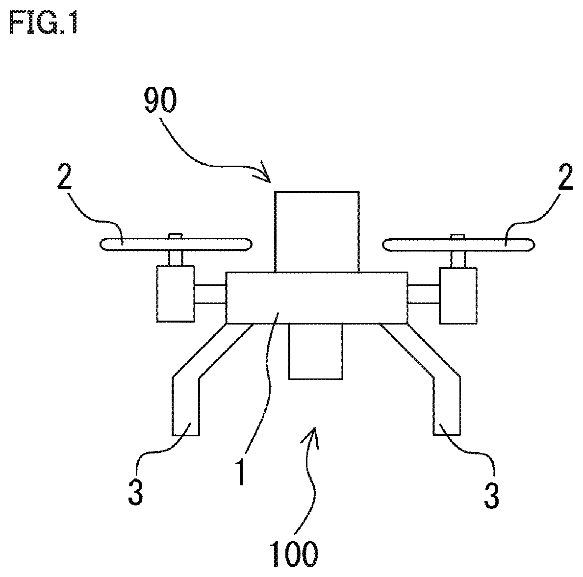
[0035]FIG. 1 is a schematic front view of an aerial vehicle 100 including an aerial vehicle safety apparatus 90 according to a First embodiment. As shown in FIG. 1, aerial vehicle 100 includes an airframe 1, at least one propulsive mechanism (for example, a propeller) 2 that is provided in airframe 1 and propels airframe 1, a plurality of legs 3 provided under airframe 1, and aerial vehicle safety apparatus 90 attached to airframe 1. Aerial vehicle safety apparatus90 is provided on airframe 1.
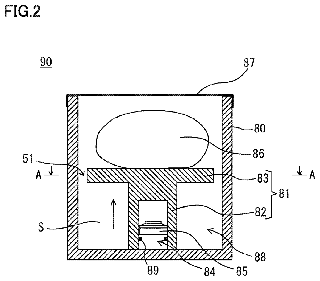
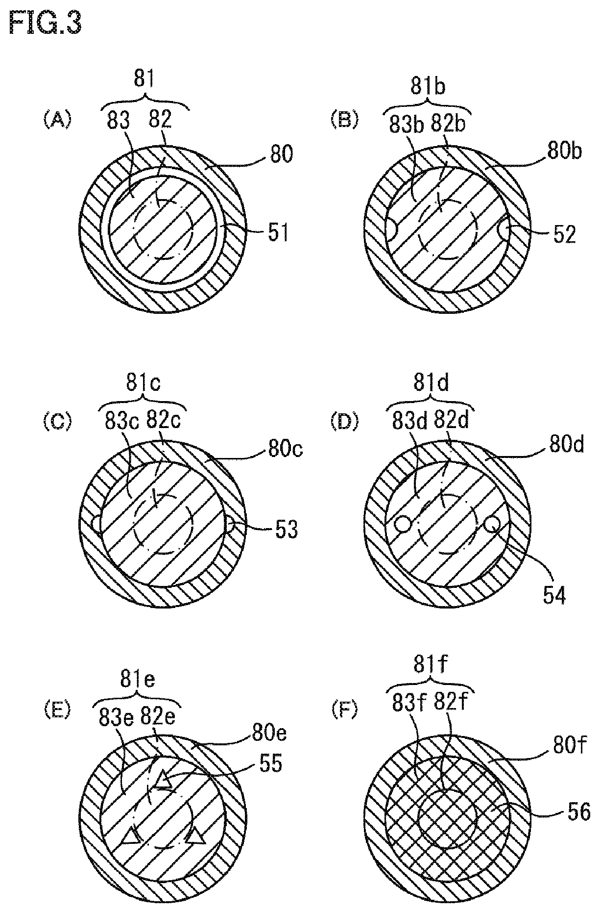
[0036]FIG. 2 is a schematic cross-sectional view of aerial vehicle safety apparatus 90 shown in FIG. 1. As shown in. FIG. 2, aerial vehicle safety apparatus 90 includes an actuator 88 as an ejection apparatus and a paraglider 86. Actuator 88 includes a gas generator (driver) 84 including a cup-shaped case 85 that a...
second embodiment
[0102]An aerial vehicle safety apparatus including a paraglider and an air bag as objects to be expanded and an aerial vehicle including the same will now be described as a second embodiment.
[0103]FIG. 7 is a schematic front view showing a state of an aerial vehicle 300 including an aerial vehicle safety apparatus 390 according to the second embodiment after an air bag 311 is expanded. Since features in FIG. 7 identical in reference numerals in last one digit to the features shown in FIG. 1 are basically the same as those described with reference to FIG. 1, description thereof may not be provided.
[0104]As shown in FIG. 7, unlike aerial vehicle safety apparatus 90 according to the first embodiment, aerial vehicle safety apparatus 390 according to the present embodiment has a main body provided under an airframe 301 of aerial vehicle 300 in a normal position and an air bag apparatus 310 which is a part of aerial vehicle safety apparatus 390 is further provided above airframe 301 in th...
third embodiment
[0111]An aerial vehicle safety apparatus including a paraglider and an air bag as objects to be expanded and an aerial vehicle including the same will now be described as a third embodiment.
[0112]FIG. 8 is a schematic front view showing a state of an aerial vehicle 400 including an aerial vehicle safety apparatus 490 according to the third embodiment after an air bag 411 is expanded. Since features in FIG. 8 identical in reference numerals in last one digit to the features shown in FIG. 1 are basically the same as those described with reference to FIG. 1, description thereof may not be provided.
[0113]As shown in FIG. 8, unlike aerial vehicle safety apparatus 90 according to the first embodiment, aerial vehicle safety apparatus 490 according to the present embodiment has an air bag apparatus 410 which is a part of aerial vehicle safety apparatus 490 provided under an airframe 401 in a normal position as being opposed to a main body of aerial vehicle safety apparatus 490 provided on a...
PUM
 Abstract
Description
Claims
Application Information
 - R&D
- Intellectual Property
- Life Sciences
- Materials
- Tech Scout
- Unparalleled Data Quality
- Higher Quality Content
- 60% Fewer Hallucinations
Browse by: Latest US Patents, China's latest patents, Technical Efficacy Thesaurus, Application Domain, Technology Topic, Popular Technical Reports.
© 2025 PatSnap. All rights reserved.Legal|Privacy policy|Modern Slavery Act Transparency Statement|Sitemap|About US| Contact US: help@patsnap.com


