Device for mounting a printing plate on a plate cylinder for a rotary printing press

a printing plate and cylinder technology, applied in the direction of office printing, printing, rotary presses, etc., can solve the problem of large angle gap in the cylinder jacket, and achieve the effect of reliable mounting, enhancing this effect, and increasing clamping for

Inactive Publication Date: 2006-08-29
MULLER MARTINI HLDG
View PDF12 Cites 1 Cited by
  • Summary
  • Abstract
  • Description
  • Claims
  • Application Information

AI Technical Summary

Benefits of technology

[0005]It is an object of the present invention to create a device of the aforementioned type which requires only a narrow plate-mounting groove while permitting a reliable mounting and holding of the printing plate on the plate cylinder, as well as a reliable ejection.
[0008]It is advantageous if the end section has an exposed edge that supports itself against one inside wall of the clamping channel and which provides the trailing end region of the printing plate with stability and rigidity. A frictional connection is thus generated inside the clamping channel between the plate cylinder and the printing plate.
[0010]It has proven advantageous if the angle between the portion of the trailing end region of the printing plate, which projects into the clamping channel, and the end section is larger prior to the insertion than in the assembled state, so that the tension generated inside the clamping channel favorably effects the securing of the trailing end region in the plate cylinder. The resulting tension generates a clamping force between the exposed end and the inside wall, wherein a sharp edge on the exposed end can favorably enhance this effect. Any attempt from the outside to pull the end region out of the clamping channel would only increase the clamping force.
[0011]According to a modified embodiment of the subject matter of this invention, the trailing end of the printing plate can be secured in place and released of a locking element assigned to the clamping channel which clamps in the exposed end of the end portion projecting through the clamping channel. In case the exposed end is unintentionally detached from the inside wall of the clamping channel, the printing plate with its end region is prevented from lifting even slightly off the plate cylinder, thereby preventing any damage to the plate cylinder. The distance between a latching nose on the locking element and the exposed end of the printing plate end portion should therefore be short.

Problems solved by technology

The disadvantage of such devices is that they require a large-angle gap in the cylinder jacket.

Method used


Image

  • Device for mounting a printing plate on a plate cylinder for a rotary printing press
  • Device for mounting a printing plate on a plate cylinder for a rotary printing press
  • Device for mounting a printing plate on a plate cylinder for a rotary printing press

Examples


Embodiment Construction

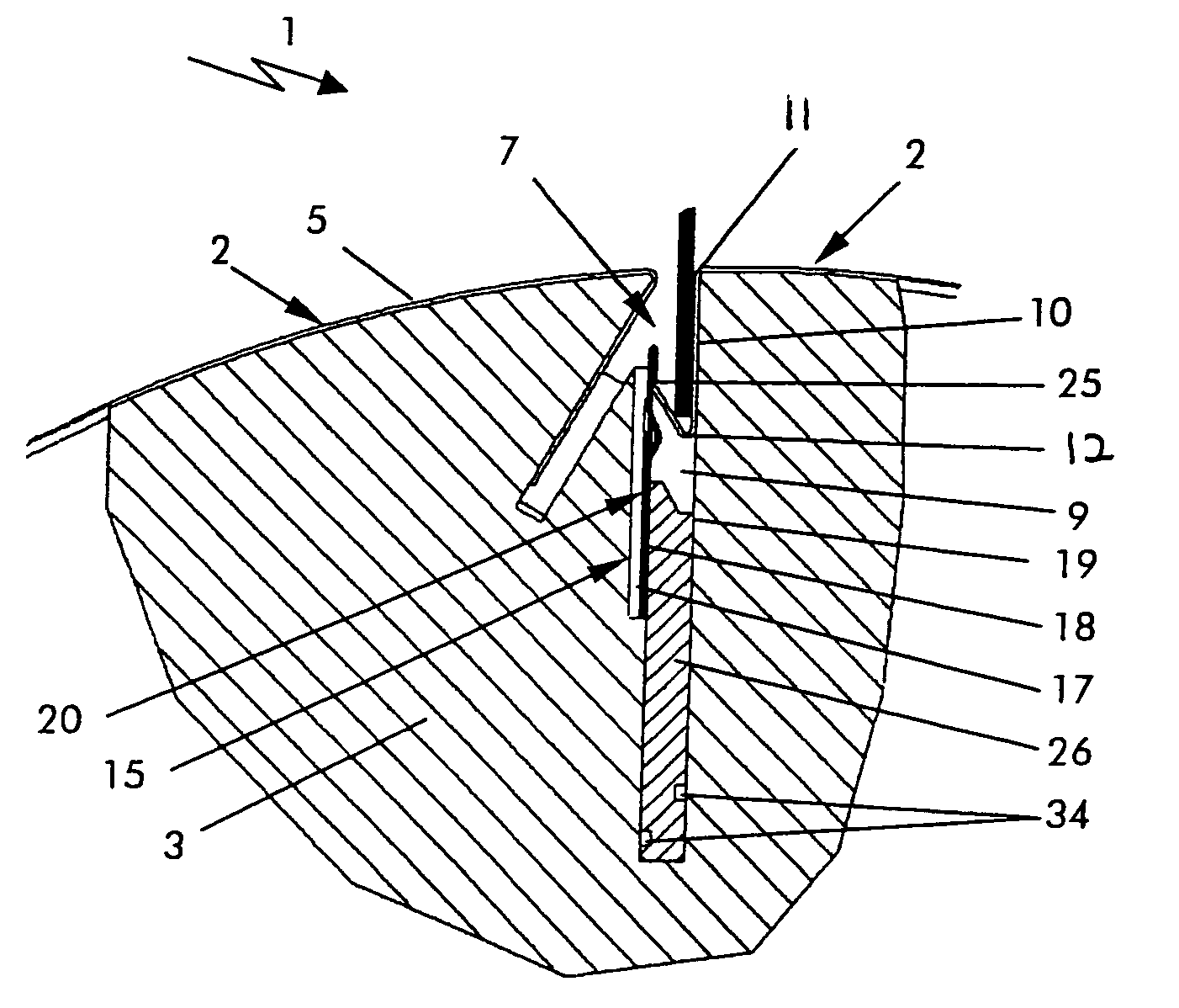
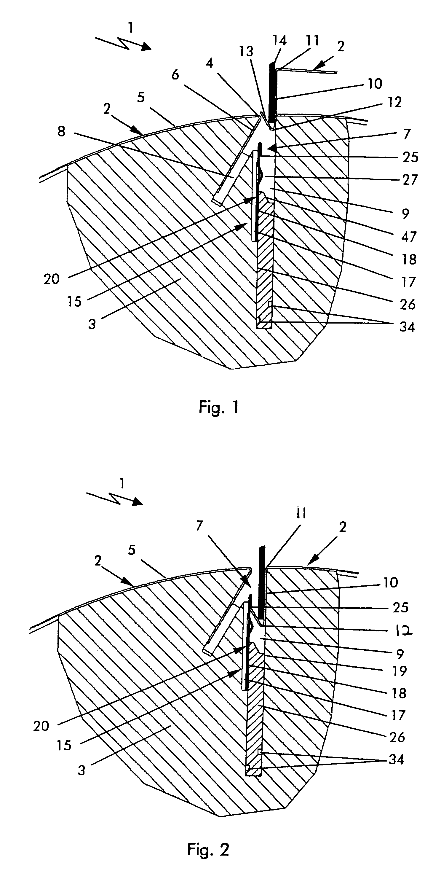
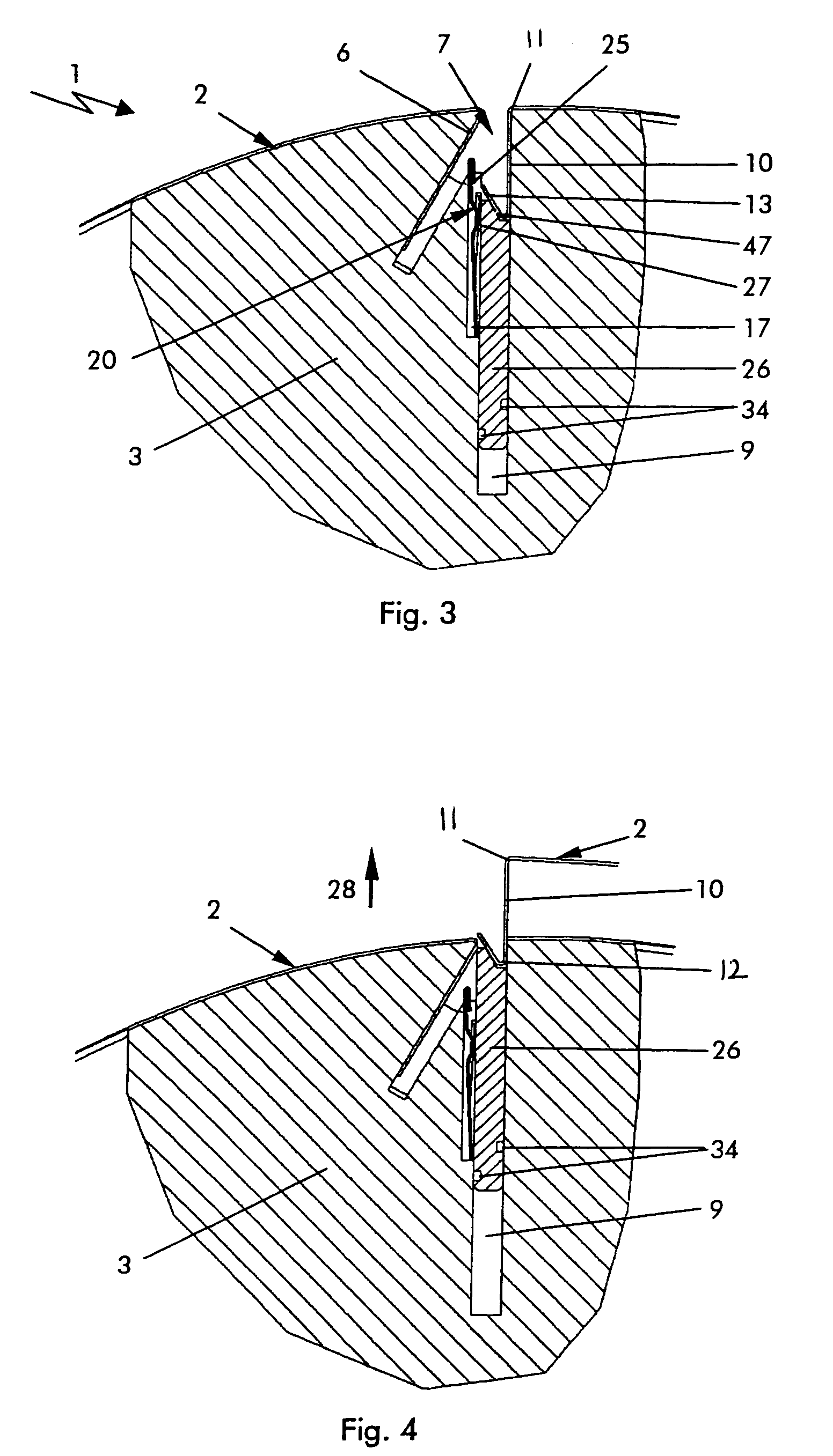
[0023]FIGS. 1 to 4 are radial cross sections of a printing plate cylinder 3 for a rotary printing press showing the steps for mounting a printing plate on the plate cylinder 3 by an arrangement 1, as well as the removal of the printing plate 2 from the plate cylinder 3.

[0024]The printing plate 2 is provided with a bent edge on the front or leading end 4 of the printing plate 2, as seen in a rotational direction F. The bent edge is formed with a section that fits against a jacket 5 of the plate cylinder and a folded end section 6 of the printing plate 2 to form an acute angle in which the leading end 4 of the printing plate 2 engages the plate cylinder 3, such that the printing plate 2 can be subsequently wound onto the plate cylinder 3. The folded section 6 projects into a channel 8 that follows a recess 7 in the plate cylinder 3.

[0025]A trailing end 10 of printing plate 2 can be secured inside an approximately radially extending clamping channel 9 which follows the recess 7.

[0026]T...


PUM


Abstract

A plate cylinder adapted for a rotary printing press has a cylinder jacket and a recess followed by a clamping channel which extend at least approximately parallel to the rotational axis of the plate cylinder inside the cylinder jacket. The printing plate has a leading end and a trailing end which are both secured inside the recess. A trailing end region of the printing plate includes two parallel bent edges extending transverse to the rotational direction of the plate cylinder. One bent edge is formed by a section of printing plate fitting against the cylinder jacket and another section of the printing plate that projects into the clamping channel which together enclose approximately a right angle. The other bent edge is formed by the section of printing plate projecting into the clamping channel and an end section of the printing plate extending through the clamping channel.

Description

CROSS-REFERENCE TO RELATED APPLICATION[0001]This application claims the priority of European Patent Application No. 04405260.3-1251, filed on Apr. 27, 2004, the subject matter of which is incorporated herein by reference. The disclosure of all U.S. and foreign patents and patent applications mentioned below are also incorporated herein by reference.BACKGROUND OF THE INVENTION[0002]The invention relates to a device for mounting a printing plate on a plate cylinder for a rotary printing press, wherein the leading end and the trailing end of the printing plate are secured inside a recess in the plate cylinder jacket that extends nearly parallel to the rotational axis of the plate cylinder.[0003]It is known to secure a folded edge of a rotating printing plate inside a recess, extending across the width of the plate cylinder and arranged parallel to the rotational axis, and to subsequently wind the printing plate around the cylinder jacket by turning the plate cylinder. The recess, posit...

Claims


Application Information

Patent Timeline
Patent Type & Authority Patents(United States)
IPC IPC(8): B41F27/12B41F13/00
CPCB41F27/1268
Inventor ZELLER, MARKUS
Owner MULLER MARTINI HLDG
Why Eureka
Try Eureka