Discharging device for vinasse tank
a technology of discharging device and vinasse tank, which is applied in the direction of liquid handling, loading/unloading, packaging, etc., can solve the problems of prolonging the service life saving cleaning time, and further reducing manpower, so as to save manpower, accurate adjustment of the height, and the stability of the vinasse tank in the lifting process and the handling process
- Summary
- Abstract
- Description
- Claims
- Application Information
AI Technical Summary
Benefits of technology
Problems solved by technology
Method used
Image
Examples
embodiment 1
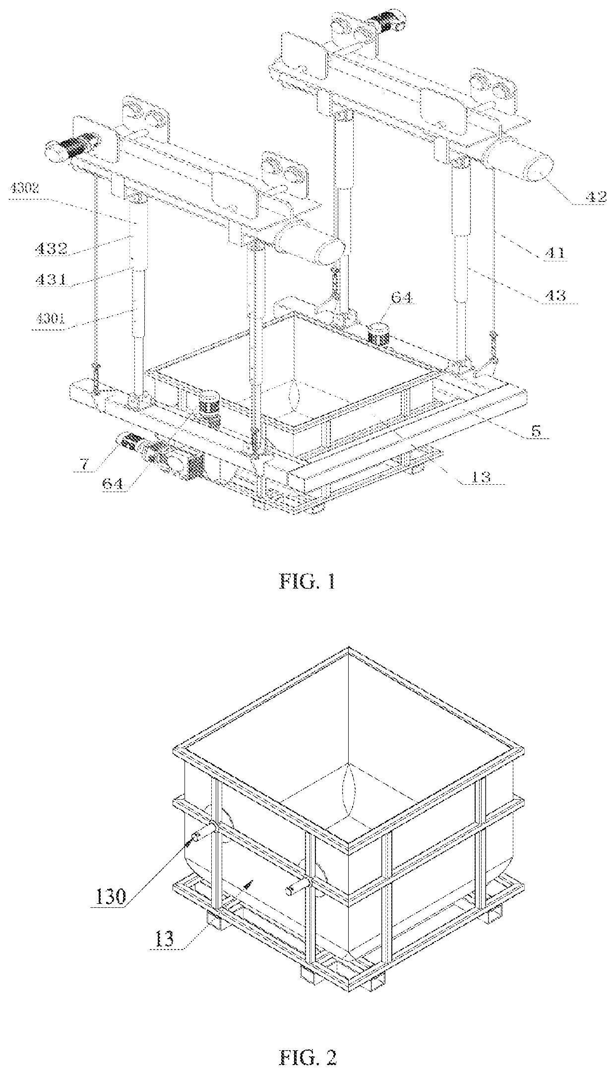
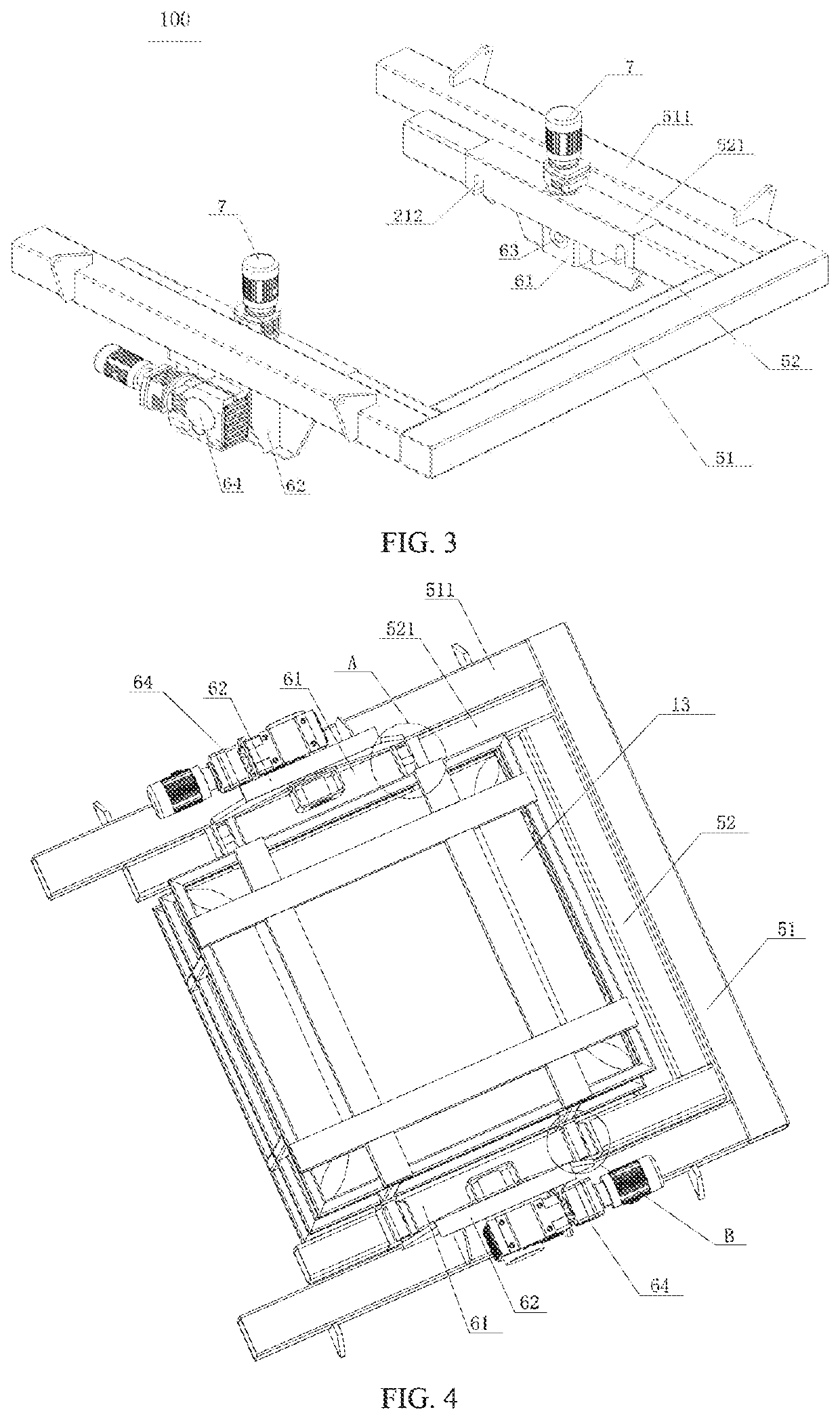
[0041]A discharging device for a vinasse tank as shown in FIG. 1 to FIG. 6 includes a flipping component 100 and a lifting component 200.
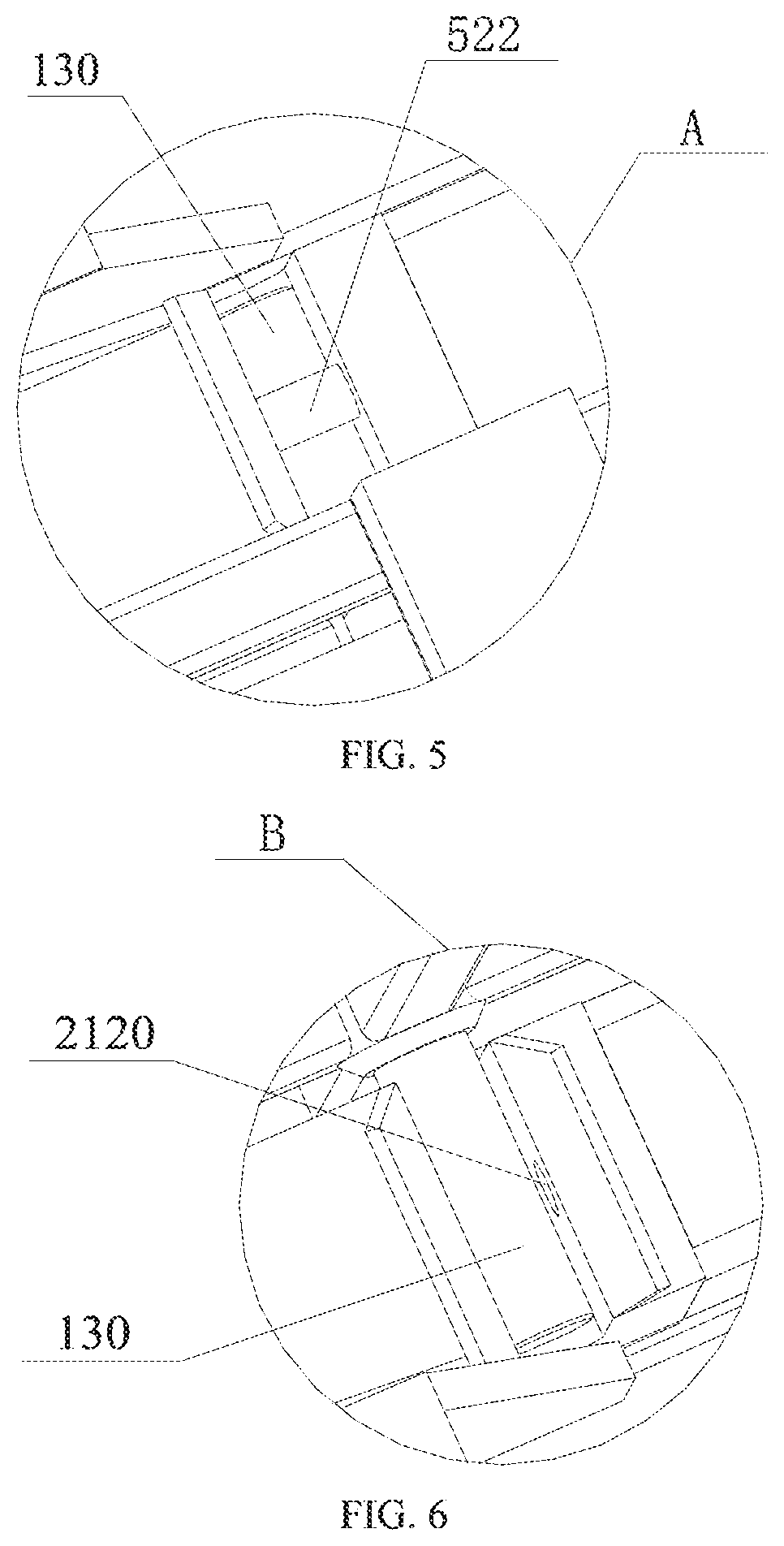
[0042]The flipping component 100 includes two groups of convex rods 130 externally connected with a group of opposite side surfaces of a vinasse tank 13, and a frame 5 matched with the shape of the vinasse tank 13. The frame 5 includes an outer frame 51 and an inner frame 52. A group of opposite inner supporting rods 521 of the inner frame 52 are provided with two groups of C-shaped grooves 212 having openings downward and opening sizes matched with the convex rods 130. Each of the C-shaped grooves 212 includes a first through hole 2120 penetrating through the lower parts of the groove walls on both sides; a gear lever 522 matched with the size of the first through hole 2120 and a first driving mechanism 300 for driving the gear lever 522 to move left and right along an axial direction of the first through hole 2120 are arranged in the inner suppor...
embodiment 2
[0046]Compared with embodiment 1, the discharging device for the vinasse tank of the present embodiment has the following differences: as shown in FIG. 8 to FIG. 11, the C-shaped groove 212 also includes a second through hole penetrating through the top wall; and the first driving mechanism 300 includes a lower movable rod 221 with a lower end passing through the second through hole, a lower end pressure structure 23 connected with the upper end of the lower movable rod 221, an upper movable rod 222, an upper end pressure structure 24 arranged on the upper movable rod 222 and capable of rotating and moving up and down, an elastic component 223, a locking structure 25, a transmission structure, and a straight toothed rod 228 penetrating through the first through hole 2120.
[0047]The transmission structure includes a primary connecting rod 224, a secondary connecting rod 225, a driving gear 226 and a driven acceleration gear 227 which are sequentially connected with the upper end of th...
PUM
 Abstract
Description
Claims
Application Information
 - R&D
- Intellectual Property
- Life Sciences
- Materials
- Tech Scout
- Unparalleled Data Quality
- Higher Quality Content
- 60% Fewer Hallucinations
Browse by: Latest US Patents, China's latest patents, Technical Efficacy Thesaurus, Application Domain, Technology Topic, Popular Technical Reports.
© 2025 PatSnap. All rights reserved.Legal|Privacy policy|Modern Slavery Act Transparency Statement|Sitemap|About US| Contact US: help@patsnap.com


