Eureka AIR delivers breakthrough ideas for toughest innovation challenges, trusted by R&D personnel around the world.

Movable temperature measurement device for secondary battery and charge/discharge apparatus comprising the same

Active Publication Date: 2020-10-29
LG ENERGY SOLUTION LTD
View PDF12 Cites 0 Cited by
  • Summary
  • Abstract
  • Description
  • Claims
  • Application Information

AI Technical Summary

Benefits of technology

The present invention is about a device that can measure the temperature of multiple batteries simultaneously, without affecting them. This is possible because the device uses an accurate non-contact temperature sensor that can measure each battery individually. By measuring the temperature quickly and non-contactedly, the device can improve the accuracy of temperature correction in capacity testing. Additionally, the device can measure multiple positions of the battery using a single sensor or multiple sensors, and store the data for research. The technical effects of this invention include improved accuracy in temperature correction and efficient measurement of battery temperature during assembly and capacity testing.

Problems solved by technology

When the temperature of the secondary batteries 1 rises, the charge / discharge operation cannot be smoothly performed.
However, when high rated charging is performed at a higher C-rate to reduce the process time, heat generation increases and the temperature deviation between the secondary batteries 1 increases.
However, in many cases, the cooling performance by the currently available air conditioner is insufficient to reduce the temperature deviation between the secondary batteries 1.

Method used


Image

  • Movable temperature measurement device for secondary battery and charge/discharge apparatus comprising the same
  • Movable temperature measurement device for secondary battery and charge/discharge apparatus comprising the same
  • Movable temperature measurement device for secondary battery and charge/discharge apparatus comprising the same

Examples


first embodiment

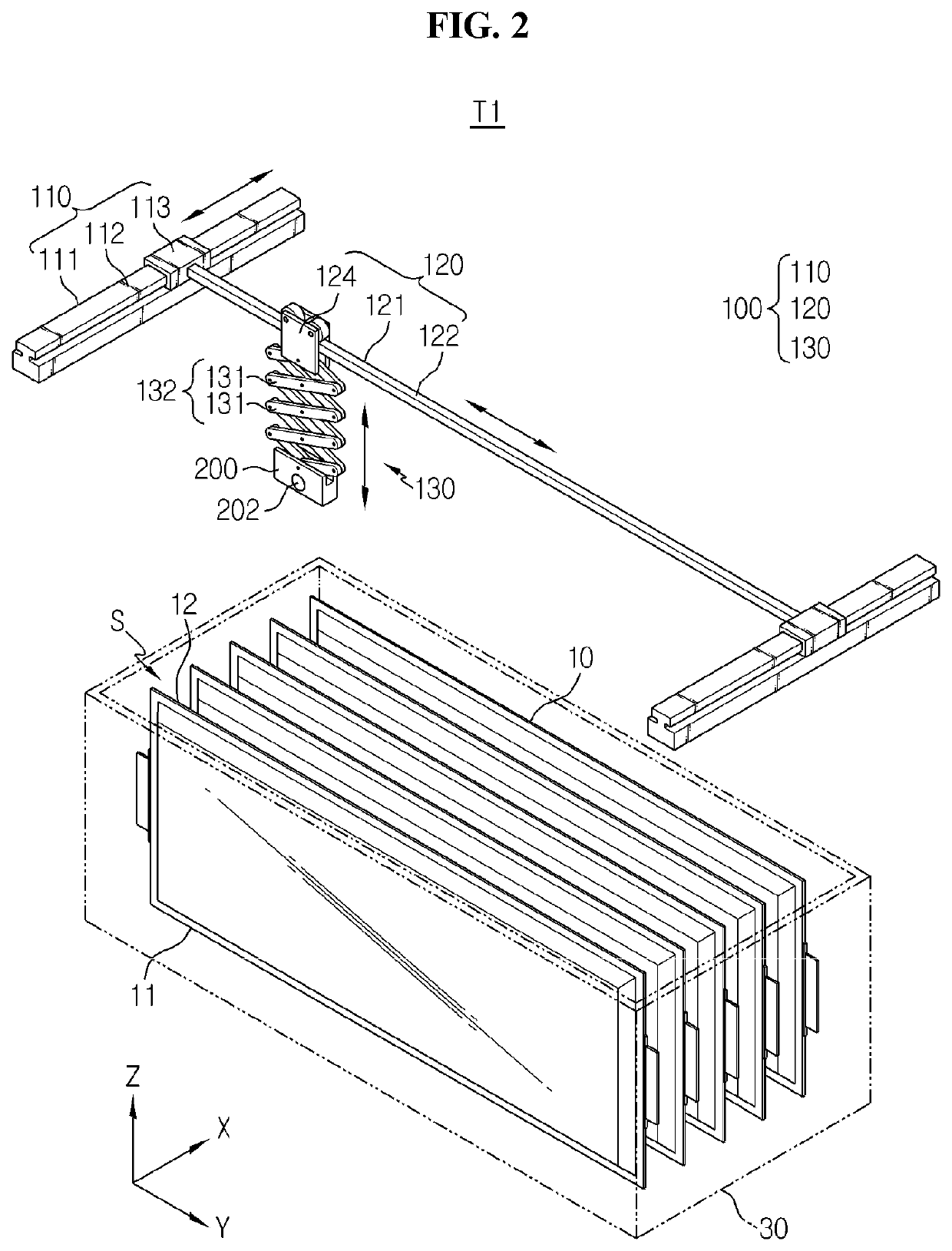
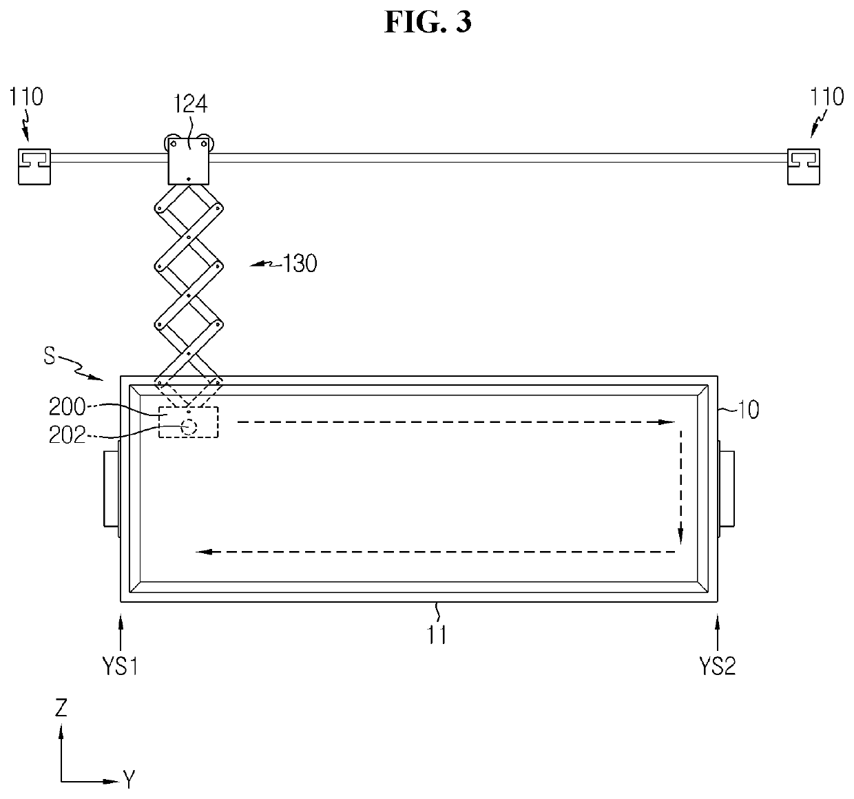
[0051]FIG. 2 shows the temperature measurement device according to the present disclosure. This embodiment is configured such that a non-contact temperature sensor may make 3-axis movements. The temperature measurement device may be installed in a tray of a charge / discharge apparatus in which a plurality of secondary batteries is mounted for capacity testing.

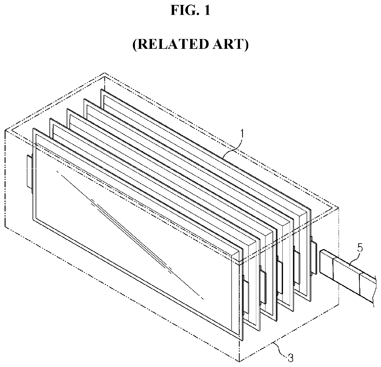
[0052]Referring to FIG. 2, the plurality of secondary batteries 10 is spaced apart from one another along X-axis direction in a standing position with one side 11 of Y-axis direction being down. For example, the secondary batteries 10 may be received and arranged in the tray 30 that may be included in the charge / discharge apparatus of the present disclosure as described below. The drawings are provided to help an understanding, and the actual number of secondary batteries in the tray may be different from those of the drawings.

[0053]The temperature measurement device T1 according to the first embodiment includes a 3-axis transfe...

third embodiment

[0067]FIG. 6 shows the temperature measurement device according to the present disclosure.

[0068]The temperature measurement device T3 according to the third embodiment includes the number of non-contact temperature sensor units 200 and Z-axis transfer devices 130 corresponding to the number of secondary batteries 10, and each non-contact temperature sensor unit 200 includes a single temperature sensor 202.

[0069]In this embodiment, after the non-contact temperature sensor units 200 including the single temperature sensors 202 move down between each of the secondary batteries 10, each non-contact temperature sensor unit 200 measures the temperature while moving horizontally and vertically by each Z-axis transfer device 130 and each Y-axis transfer device 120, then moves back up, and in this way, the temperature of all the secondary batteries 10 may be measured, and there is no need to transfer the Z-axis transfer device 130 in X-axis direction. The number of single temperature sensors...

sixth embodiment

[0083]Referring to FIG. 11, in the temperature measurement device T6 of the sixth embodiment, the non-contact temperature sensor unit 230 includes a plate member 231 of an area corresponding to the area on the Y-Z plane of the secondary batteries 10 and multiple temperature sensors 232 arranged along the Y-axis and Z-axis on the plate member 231, and as shown in FIG. 12, the non-contact temperature sensor unit 230 is moved down between the secondary batteries 10 and inserted into the spacing S, simultaneously measures the temperature of many positions over the area on the Y-Z plane of the secondary battery 10 that the non-contact temperature sensor unit 230 faces, then is taken out. The use of the plurality of sensors may reduce the measurement time.

[0084]The non-contact temperature sensor unit 230 measures the temperature from one side of X-axis direction, and as the Z-axis transfer device 130 is transferred by the X-axis transfer device 110, the temperature measurement is performe...


PUM


Abstract

A temperature measurement device suitable for measuring the temperature of each secondary battery to consider a temperature deviation between secondary batteries that may occur during charging / discharging in the formation process and capacity test after the secondary battery assembly process, and a charge / discharge apparatus including the temperature measurement device are provided. The temperature measurement device is for measuring a temperature of at least one of a plurality of secondary batteries arranged along an X-axis direction, spaced apart from one another, in a standing position, and includes a non-contact temperature sensor unit which is insertable into a spacing between adjacent secondary batteries to measure the temperature of the secondary battery that the non-contact temperature sensor unit faces in a non-contact manner, and a Z-axis transfer device which inserts the non-contact temperature sensor unit into the spacing downward from above the secondary batteries in a Z-axis direction.

Description

TECHNICAL FIELD[0001]The present disclosure relates to a device for measuring the temperature of a secondary battery and a charge / discharge apparatus comprising the same. The present application claims the benefit of Korean Patent Application No. 10-2018-0067737 filed on Jun. 12, 2018 with the Korean Intellectual Property Office, the disclosure of which is incorporated herein by reference in its entirety.BACKGROUND ART[0002]With the technology development and the growing demand for mobile devices, electric vehicles, hybrid electric vehicles, energy storage systems (ESSs) and uninterrupted power systems (UPS), secondary batteries as a source of energy are in dramatically increasing demand, and to meet various demands, many studies have been made on secondary batteries.[0003]Because an assembly process is performed on a secondary battery in discharged state, the assembled secondary battery is charged for activation to work as a battery. Accordingly, the secondary battery assembly proc...

Claims


Application Information

Patent Timeline
IPC IPC(8): G01J5/02G01J5/10H01M10/44
CPCH01M10/443G01J5/10G01J5/0205Y02E60/10H01M10/486G01J5/047
Inventor LEE, BEOM-KOONPARK, HYO-JINBAE, DONG-HUNBAE, JOON-SUNGLEE, EUI-KYUNGHONG, SUK-HYUN
Owner LG ENERGY SOLUTION LTD
Why Eureka
Eureka Blog
Learn More