Eureka AIR delivers breakthrough ideas for toughest innovation challenges, trusted by R&D personnel around the world.

Method for examining a magnetic field source

Active Publication Date: 2020-05-21
FRAUNHOFER GESELLSCHAFT ZUR FOERDERUNG DER ANGEWANDTEN FORSCHUNG EV
View PDF0 Cites 1 Cited by
  • Summary
  • Abstract
  • Description
  • Claims
  • Application Information

AI Technical Summary

Benefits of technology

The patent describes a method and apparatus for accurately measuring the magnetic field source of a magnetic field. The method involves detecting the magnetic vector field and the geometrical body of the magnetic field source in separate coordinate systems and combining them into a mutual coordinate system using a coordinate transformation. This allows for the accurate positioning of the magnetic vector field and the geometrical body of the magnetic field source in relation to each other. The technical effect of this invention is the ability to quickly and accurately measure and characterize magnetic field sources, even if the geometry is not perfectly known.

Problems solved by technology

If detected, these deviations of the magnetic field lead to rejects when assembling the total magnetic system.
Undetected, they lead to errors in the later use up to the failure of the total system.
The influence of these error sources is difficult to control.
However, these inspection systems may only be used to check whether the magnetic field of a magnetic encoder is within a tolerance range or not.
In this case, the total system is examined for proper functioning, wherein, in the worst case, unserviceability of the system is diagnosed and a large number of rejects is generated.
Due to the full integration, the replacement of erroneous magnetic encoders in systems is not always possible and causes high costs.
This process of calibration compensates for errors of the encoder; however, it may not completely compensate for excessive deviations from the nominal values, e.g. if an incorrect magnetic field has been applied to a magnet.
Through this approach, erroneous geometries and erroneous magnetizations may be quickly and simply identified.

Method used


Image

  • Method for examining a magnetic field source
  • Method for examining a magnetic field source
  • Method for examining a magnetic field source

Examples


Embodiment Construction

[0017]In the following, embodiments are described in more detail with respect to the figures, wherein elements having the same or similar functions are provided with the same reference numerals.

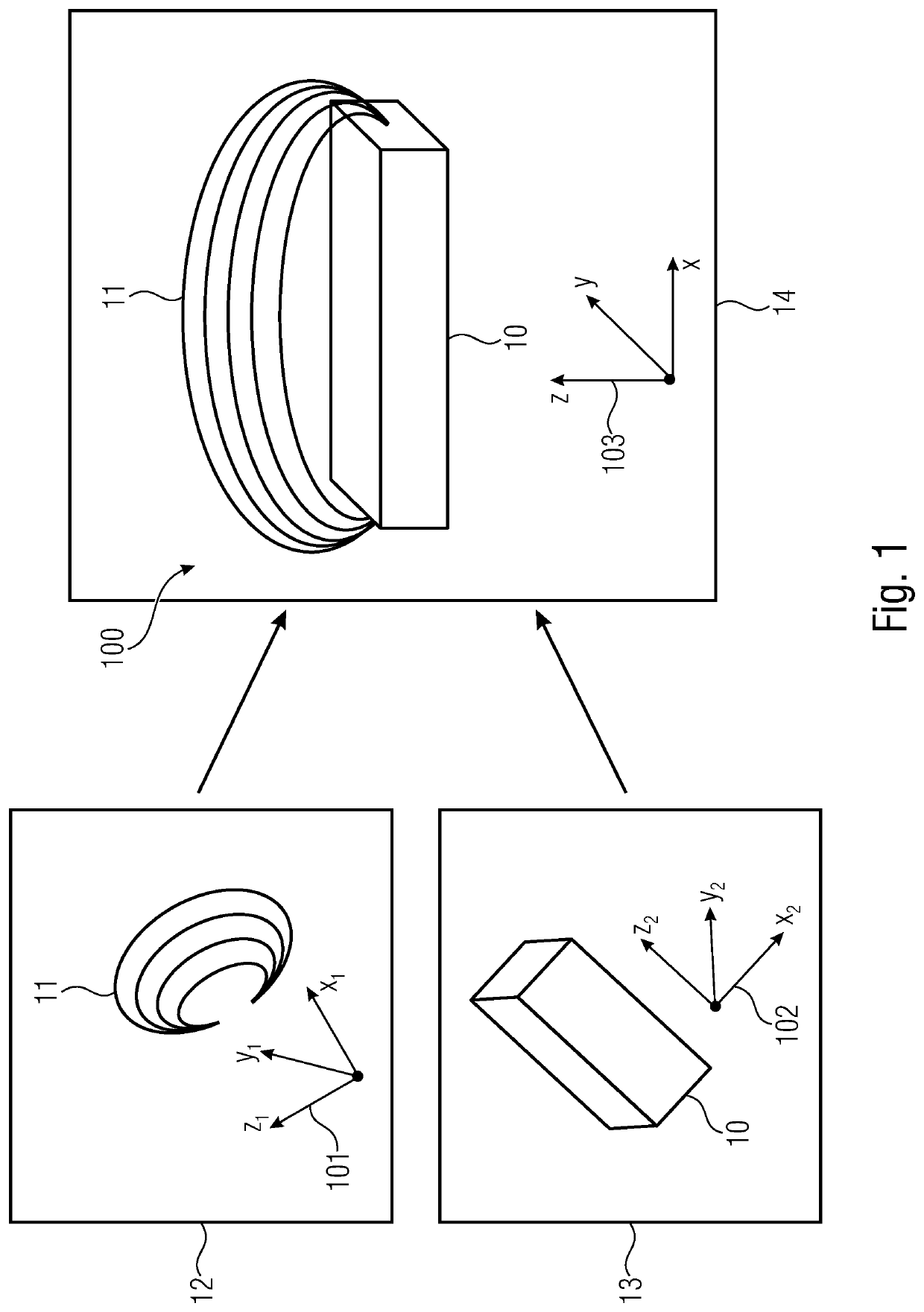
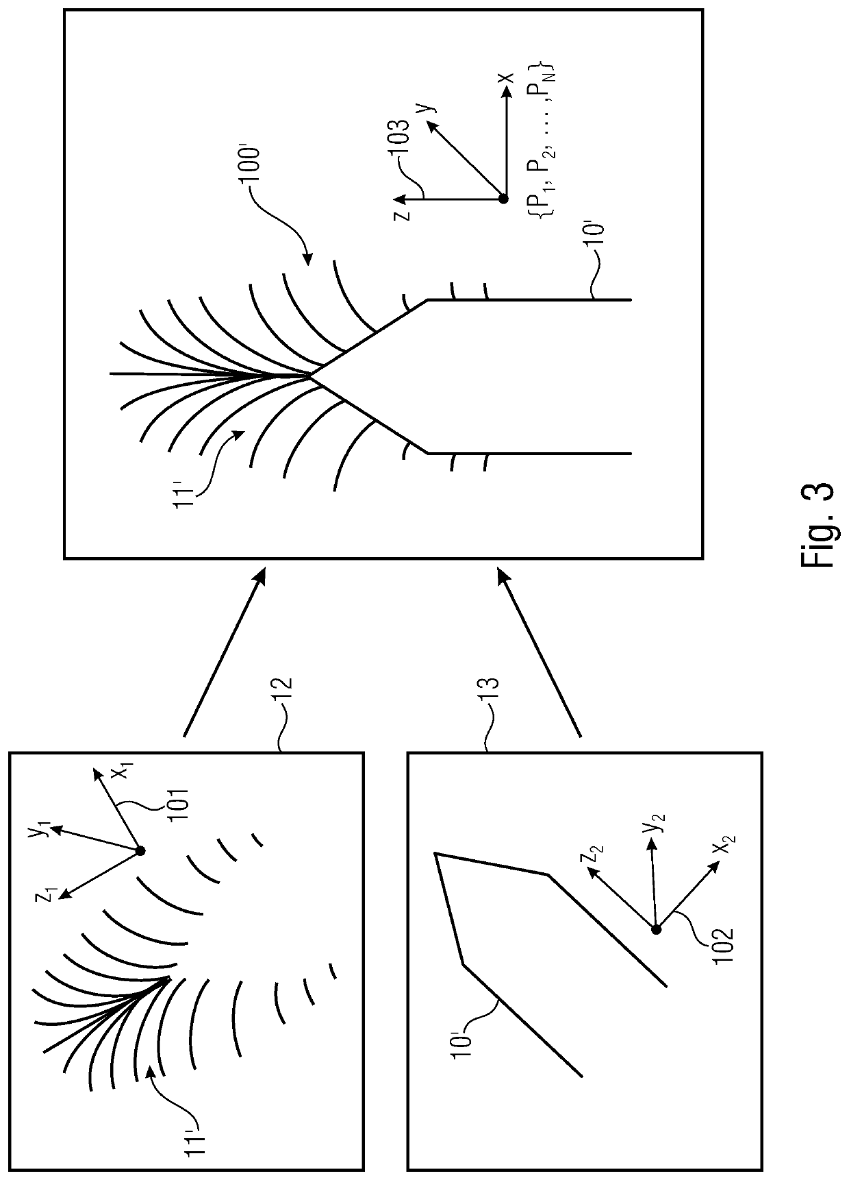
[0018]The terms magnetic field source, source and magnetic encoder, or encoder, are synonymously used herein. In principle, everything that is described with respect to the magnetic field source 100 and the geometrical body 10 of the magnetic field source 100 also applies to the reference magnetic field source 100′ and the geometrical body 10′ of the reference magnetic field source 100′, and vice versa.

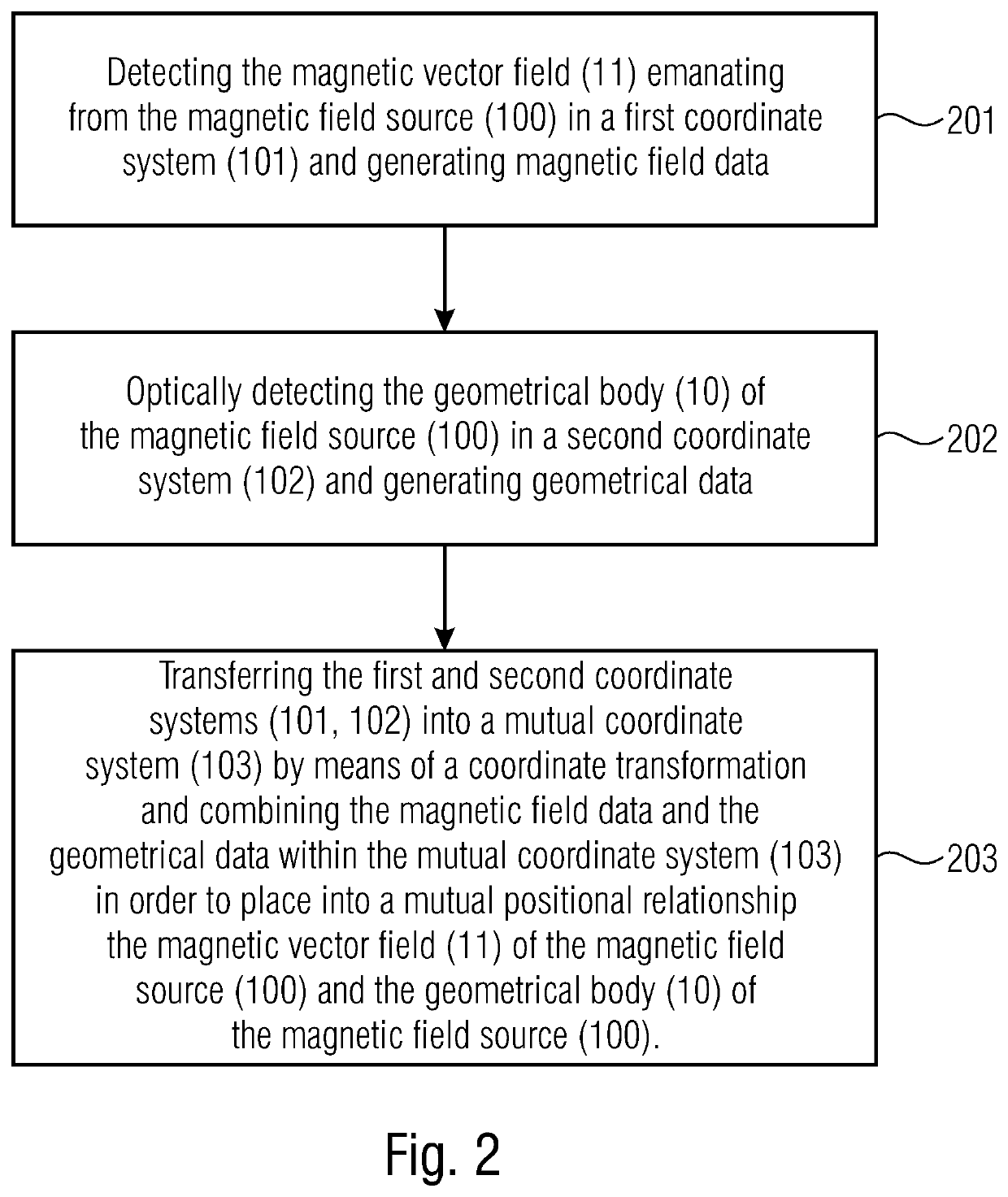
[0019]Method steps that are illustrated in a block diagram and described with respect to the same may be performed in any other order than in the illustrated and / or described order. In addition, method steps concerning a certain feature of an apparatus are interchangeable with the same feature of the apparatus, and vice versa.

[0020]FIG. 1 shows a schematic representation of the inventive method...


PUM


Abstract

The invention relates to a method for examining a magnetic field source. In this case, the magnetic vector field emanating from the magnetic field source is detected in a first coordinate system and corresponding magnetic field data is generated. Furthermore, the geometrical body of the magnetic field source is geometrically detected in a second coordinate system and corresponding geometrical data is generated. Subsequently, the first and the second coordinate systems are transferred into a mutual coordinate system by means of a coordinate transformation and the magnetic field data and the geometrical data are combined within the mutual coordinate system in order to place the magnetic vector field of the magnetic field source and the geometrical body of the magnetic field source into a mutual positional relationship.

Description

CROSS-REFERENCE TO RELATED APPLICATION[0001]This application claims priority from German Patent Application No. DE 10 2018 219 722.9, which was filed on Nov. 16, 2018, and is incorporated herein in its entirety by reference.BACKGROUND OF THE INVENTION[0002]The invention relates to a method for characterizing, or examining, a magnetic field source. For this, in embodiments, magnetic field data and geometrical data of a magnetic field source are collected and transferred into a mutual coordinate system. This enables the precise positional assignment of the magnetic vector field in relation to the geometry, i.e. to the geometrical body, of the magnetic field source.[0003]Both, permanent magnets and other magnetic devices (e.g. coils) may be used as single magnetic components, and in particular as magnetic sources or encoders, for the assembly of total magnetic systems. These magnetic single components are used in large quantities, e.g. in machine technology or position sensor technolog...

Claims


Application Information

Patent Timeline
IPC IPC(8): G01R33/02H01F7/02
CPCH01F7/0294G01R33/02G01R33/12G01N24/08G01R33/10
Inventor BERAN, PHILIPTISCHLINGER, GERHARD
Owner FRAUNHOFER GESELLSCHAFT ZUR FOERDERUNG DER ANGEWANDTEN FORSCHUNG EV
Why Eureka
Eureka Blog
Learn More