Eureka AIR delivers breakthrough ideas for toughest innovation challenges, trusted by R&D personnel around the world.

Charging and discharging apparatus including cooling fan and movable temperature measuring device for secondary battery

Active Publication Date: 2021-07-22
LG ENERGY SOLUTION LTD
View PDF0 Cites 0 Cited by
  • Summary
  • Abstract
  • Description
  • Claims
  • Application Information

AI Technical Summary

Benefits of technology

The present invention provides a method for measuring the temperature of multiple secondary batteries simultaneously, using non-contact temperature sensors. By measuring the temperature of each secondary battery individually, temperature deviations between the batteries can be considered when calculating capacity, improving accuracy. The non-contact temperature sensor unit can be quickly and accurately measure the temperature, and a movable temperature measuring device can be provided to measure the temperature of each battery using a small number of sensors. The measured temperatures can be recorded to create a database, and the direction of the wind and output of cooling fan can be adjusted based on the temperature information to ensure uniform charging and discharging quality.

Problems solved by technology

When the temperature of the secondary battery 1 is increased, the charging and discharging operation is unable to be smoothly performed.
However, when high-rate charging is performed with a larger C-rate to reduce a process time, heat generation increases, thereby increasing the temperature deviation between the secondary batteries 1.
However, a current degree of cooling by the cooling fan 5 is often insufficient to reduce the temperature deviation between the secondary batteries 1.
Moreover, since the cooling fan 5 currently used to adjust the temperature operates at the same output regardless of the actual temperature of the secondary battery, the cooling fan 5 is not helpful in reducing the temperature deviation.
The temperature deviation between the secondary batteries 1 causes a change in the resistance and voltage, thereby causing an increase in the capacity test deviation.

Method used


Image

  • Charging and discharging apparatus including cooling fan and movable temperature measuring device for secondary battery
  • Charging and discharging apparatus including cooling fan and movable temperature measuring device for secondary battery
  • Charging and discharging apparatus including cooling fan and movable temperature measuring device for secondary battery

Examples


first embodiment

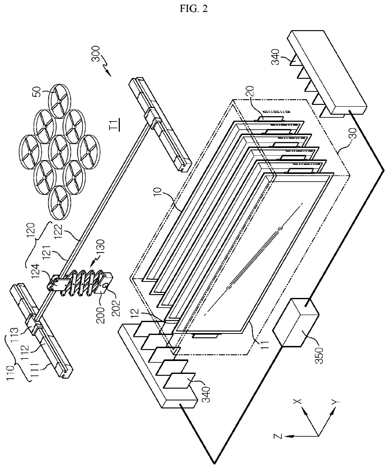
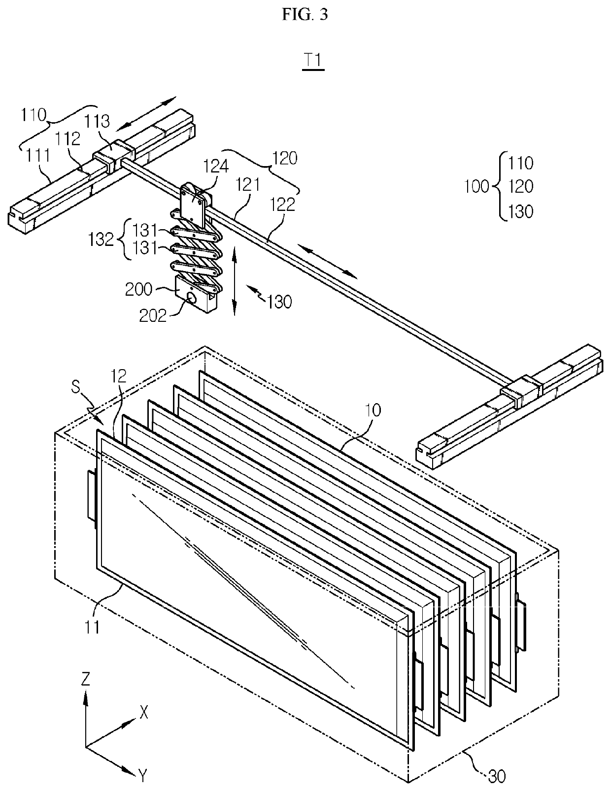
[0057]FIG. 2 illustrates a charging and discharging apparatus according to the present disclosure. In the current embodiment, a non-contact temperature sensor includes a temperature measuring device configured to move in three axes and a plurality of cooling fans of which directions of wind and outputs are individually adjusted according to temperature information measured by the temperature measuring device.

[0058]First, the charging and discharging apparatus 300 includes a tray 30 in which a plurality of secondary batteries 10 spaced apart from each other along an X-axis direction while being erected with one side 11 in a Y-axis direction at a bottom thereof are arranged and accommodated. Also, the charging and discharging apparatus 300 includes the temperature measuring device T1. A charging and discharging probe 340 and a power supplier 350 for applying power individually to the secondary batteries 10 accommodated in the tray 30 are also included. The plurality of cooling fans 50...

third embodiment

[0089]FIG. 8 illustrates the temperature measuring device that may be included in a charging and discharging apparatus, according to the present disclosure.

[0090]In the temperature measuring device T3 shown in FIG. 8, the Z-axis transfer devices 130 and the non-contact temperature sensor units 200, each including the single temperature sensor 202, are provided as many as the number corresponding to the number of secondary batteries 10.

[0091]In the current embodiment, the non-contact temperature sensor units 200 including the single temperature sensors 202 may descend between the secondary batteries 10 and measure temperatures of all secondary batteries 10 as each non-contact temperature sensor unit 200 is moved up, down, left, and right by the respective Z-axis transfer device 130 and Y-axis transfer device 120 to measure a temperature and ascends again, and the Z-axis transfer device 130 is not required to be transferred in the X-axis direction. Since the plurality of single temper...

fourth embodiment

[0096]FIG. 10 is a diagram for describing a method of measuring a temperature of one secondary battery by using the temperature measuring device T4 included in the charging and discharging apparatus, according to the present disclosure.

[0097]Referring to FIG. 10, the non-contact temperature sensor unit 210 descends between the secondary batteries 10 to be inserted into the space S at the one side YS1 in the Y-axis direction, is transferred up to the other side YS2 Y-axis direction by the Y-axis transfer device 120, and then withdrawn from the space S, and sequentially measures temperatures of several locations of the facing secondary battery 10 with respect to an area on the Y-Z plane while being transferred in the space S.

[0098]Meanwhile, as a modification of the fourth embodiment, the Z-axis transfer device 140 according to the second embodiment may be provided instead of the Z-axis transfer device 130. Also, as a modification of the fourth embodiment, a temperature measuring devi...


PUM


Abstract

A charging and discharging apparatus including a temperature measuring device suitable for measuring a temperature of each secondary battery and a cooling fan for cooling secondary batteries by utilizing temperature information using the temperature measuring device, such that a temperature deviation between the secondary batteries, which may occur during charging and discharging in a formation process and a capacity test after a secondary battery assembly process, is provided. The charging and discharging apparatus includes a movable non-contact temperature measuring device and cooling fans of which directions of wind and outputs are individually adjusted based on temperature information measured by the temperature measuring device according to a location in each secondary battery.

Description

TECHNICAL FIELD[0001]The present disclosure relates to a charging and discharging apparatus for a secondary battery, and more particularly, to a charging and discharging apparatus including a device for measuring a temperature of a secondary battery and a cooling fan for cooling the secondary battery according to the temperature measured by the device.[0002]The present application claims priority to Korean Patent Application No. 10-2018-0167882 filed on Dec. 21, 2018 in the Republic of Korea, the disclosures of which are incorporated herein by reference.BACKGROUND ART[0003]With the increase in technology development and demands for movable devices, electric vehicles, hybrid vehicles, energy storage systems (ESSs), uninterrupted power system (UPS), and the like, demands for secondary batteries as energy sources are rapidly increasing and accordingly, many studies on secondary batteries that meet various requirements are being conducted.[0004]Since the secondary batteries are assemble...

Claims


Application Information

Patent Timeline
IPC IPC(8): H02J7/00H01M10/6563H01M10/613
CPCH02J7/007194H01M10/613H02J7/00309H01M10/6563H01M10/44Y02E60/10H01M10/441H01M10/446H01M10/486H01M10/48H01M10/65H01M10/4285H01M4/0447G01R31/36
Inventor LEE, BEOM-KOONPARK, HYO-JINBAE, DONG-HUNBAE, JOON-SUNGLEE, EUI-KYUNGHONG, SUK-HYUN
Owner LG ENERGY SOLUTION LTD
Why Eureka
Eureka Blog
Learn More