System and Program for Setting Flight Plan Route of Unmanned Aerial Vehicle

a technology for unmanned aerial vehicles and flight plans, applied in vehicle position/course/altitude control, process and machine control, instruments, etc., can solve time-consuming problems, achieve easy and reliable reduction of structure, and communicate reliably to users

Pending Publication Date: 2020-10-29
ACSL LTD
View PDF6 Cites 2 Cited by
  • Summary
  • Abstract
  • Description
  • Claims
  • Application Information

AI Technical Summary

Benefits of technology

[0012]The present invention has an advantageous effect that a 3D flight plan route can be determined only by inputting positions of waypoints on a horizontal plane, because data indicating a scheduled flight route of an unmanned aerial vehicle on a horizontal plane is inputted; a height reference value indicating an elevation of a surface under each of a plurality of positions on the flight plan route is acquired; and values obtained by adding flight altitudes corresponding to the positions to the height reference values, respectively, are determined as altitude data on the flight plan route.
[0013]The present invention has an advantageous effect that a 3D flight plan route can be determined without needing inputs of elevations of ground surfaces along the flight plan route when the present invention includes the component that reads, from the geographic database, an elevation of a ground surface under each of the plurality of positions on the flight plan route in the horizontal plane as the height reference value. The present invention has an advantageous effect that a flight plan route can be set within a room inside a building when the present invention includes the component that reads, from the database, an altitude of a floor surface inside a building under each of the plurality of positions on the flight plan route in the horizontal plane as the height reference value. The present invention has an advantageous effect that a proximate position that is at risk for collision if a flight is conducted along a flight plan route can be identified when the present invention includes the component that identifies, on any entity on the ground surface, a proximate place at which a distance from the flight plan route is equal to or less than a predetermined safe distance. The present invention has an advantageous effect that a positional relationship between a flight plan route and a proximate place can be appropriately communicated to a user when the present invention includes the component that outputs a distance and an orientation from a position on the flight plan route corresponding to the identified proximate place to the identified proximate place. The present invention has an advantageous effect that existence of a proximate place at risk for collision can be reliably communicated to a user when the present invention includes the component that issues a warning when the proximate place is identified.
[0014]The present invention has an advantageous effect that a possibility of collision of an unmanned aerial vehicle against an obstacle such as a structure can be easily and reliably reduced when the present invention includes the component that corrects the flight plan route such that the proximate place is avoided. The present invention has an advantageous effect that a flight plan route can be automatically set such that an unmanned aerial vehicle keeps a distance that is not less than a safe distance from an obstacle such as a structure when the present invention includes the component that automatically corrects the flight plan route such that a distance between the flight plan route and the proximate place becomes the safe distance or greater. The present invention has an advantageous effect that a flight plan route can be c...

Problems solved by technology

When many waypoints are inputted, it can be time-consuming work to input an altitude above ground level of a waypoint, for each of the waypoint...

Method used


Image

  • System and Program for Setting Flight Plan Route of Unmanned Aerial Vehicle
  • System and Program for Setting Flight Plan Route of Unmanned Aerial Vehicle
  • System and Program for Setting Flight Plan Route of Unmanned Aerial Vehicle

Examples


Embodiment Construction

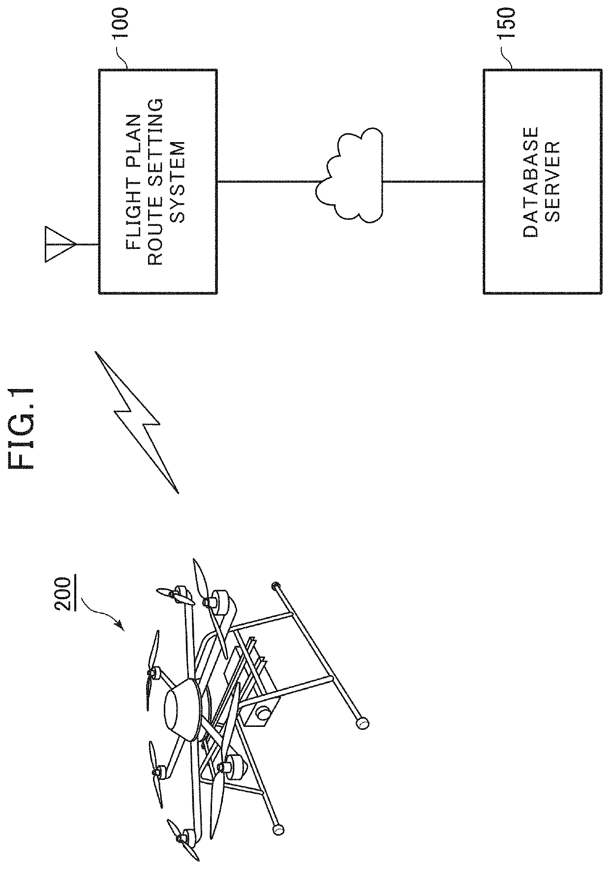
[0036]Hereinafter, a flight plan route setting system 100 for setting a 3D flight plan route of an unmanned aerial vehicle, as an embodiment of the present invention, will be described with reference to drawings. However, the present invention is not limited to specific aspects as described below, and can take various aspects within the scope of technical ideas of the present invention. For example, an unmanned aerial vehicle to which the present invention is applied is not limited to a multicopter as shown in FIG. 1, but may be any unmanned aerial vehicle such as a rotorcraft or a fixed-wing aircraft and does not need to be an unmanned aerial vehicle of autonomous-flight type. A system configuration of the flight plan route setting system is not limited to a configuration shown in drawings, but any configuration may be made as long as similar operations are possible. For example, operations performed by a plurality of components may be performed by a single component, such as by in...


PUM


Abstract

A 3D flight plan route is set based on an inputted scheduled flight route of an unmanned aerial vehicle. A system for setting a 3D flight plan route of an unmanned aerial vehicle according to the present invention is characterized by: inputting data indicating a scheduled flight route of the unmanned aerial vehicle on a horizontal plane; acquiring a height reference value indicating an elevation of a surface under each of a plurality of positions on the flight plan route; and determining values obtained by adding flight altitudes corresponding to the positions to the height reference values, respectively, as altitude data on the flight plan route.

Description

TECHNICAL FIELD[0001]The present invention relates to a system for setting a flight plan route of an unmanned aerial vehicle and, more particularly, to a system for setting a 3D flight plan route based on an inputted scheduled flight route of an unmanned aerial vehicle.BACKGROUND ART[0002]When a flight of an unmanned aerial vehicle is conducted, a flight plan is arranged by setting a 3D flight plan route of the unmanned aerial vehicle before the flight. For the setting, waypoints that are a plurality of positions defining the 3D flight plan route are inputted. In such a case, in general, X-, Y-coordinates that are positions of the waypoints on a horizontal plane are inputted by specifying the positions on a map, and Z-coordinates that are altitudes of the waypoints are inputted by inputting numerical values.[0003]A Z-coordinate of a waypoint is commonly specified by a relative distance above a ground surface immediately under the waypoint, that is, an altitude above ground level. Th...

Claims


Application Information

Patent Timeline
IPC IPC(8): G08G5/00G05D1/00G06F16/29B64C39/02
CPCB64C39/024G06F16/29G05D1/0038G08G5/0086G08G5/0039B64C2201/127G08G5/0034G08G5/0069G01C21/20G08G5/0013G08G5/0026G08G5/045G05D1/102G05D1/0646B64U10/16B64U2101/30B64U60/50
Inventor SHINYA, KENJI
Owner ACSL LTD
Why Eureka
Try Eureka