Eureka AIR delivers breakthrough ideas for toughest innovation challenges, trusted by R&D personnel around the world.

Gripper for spools

a spool and spool technology, applied in the field of spool grippers, can solve the problems of complex and dynamic production environment, time-consuming location of the centre, and use of relatively expensive ccd cameras

Active Publication Date: 2020-11-05
NV BEKAERT SA
View PDF0 Cites 0 Cited by
  • Summary
  • Abstract
  • Description
  • Claims
  • Application Information

AI Technical Summary

Benefits of technology

The invention provides a gripper that can quickly and accurately determine the center of a spool and grip it securely. This is achieved through the use of sensors that detect the presence of a spool and guide the gripper to its center. The gripper is designed to work in industrial environments and is particularly suitable for finding and gripping spools. The sensors are affordable and can detect the distance between the gripper and the reflecting body on the spool, which helps to locate the center of the spool more quickly and efficiently. The gripper's design also prevents it from moving back after identifying the center position of the spool. Overall, the invention aims to improve the speed and accuracy of spool determination and gripping in industrial settings.

Problems solved by technology

When automating the task of picking up a full or empty spool engineers are confronted with a complex and dynamic production environment.
Such methods require the use of CCD cameras that are relatively expensive.
This makes the location of the centre time-consuming as a meandering path must be followed.

Method used


Image

  • Gripper for spools
  • Gripper for spools
  • Gripper for spools

Examples


Embodiment Construction

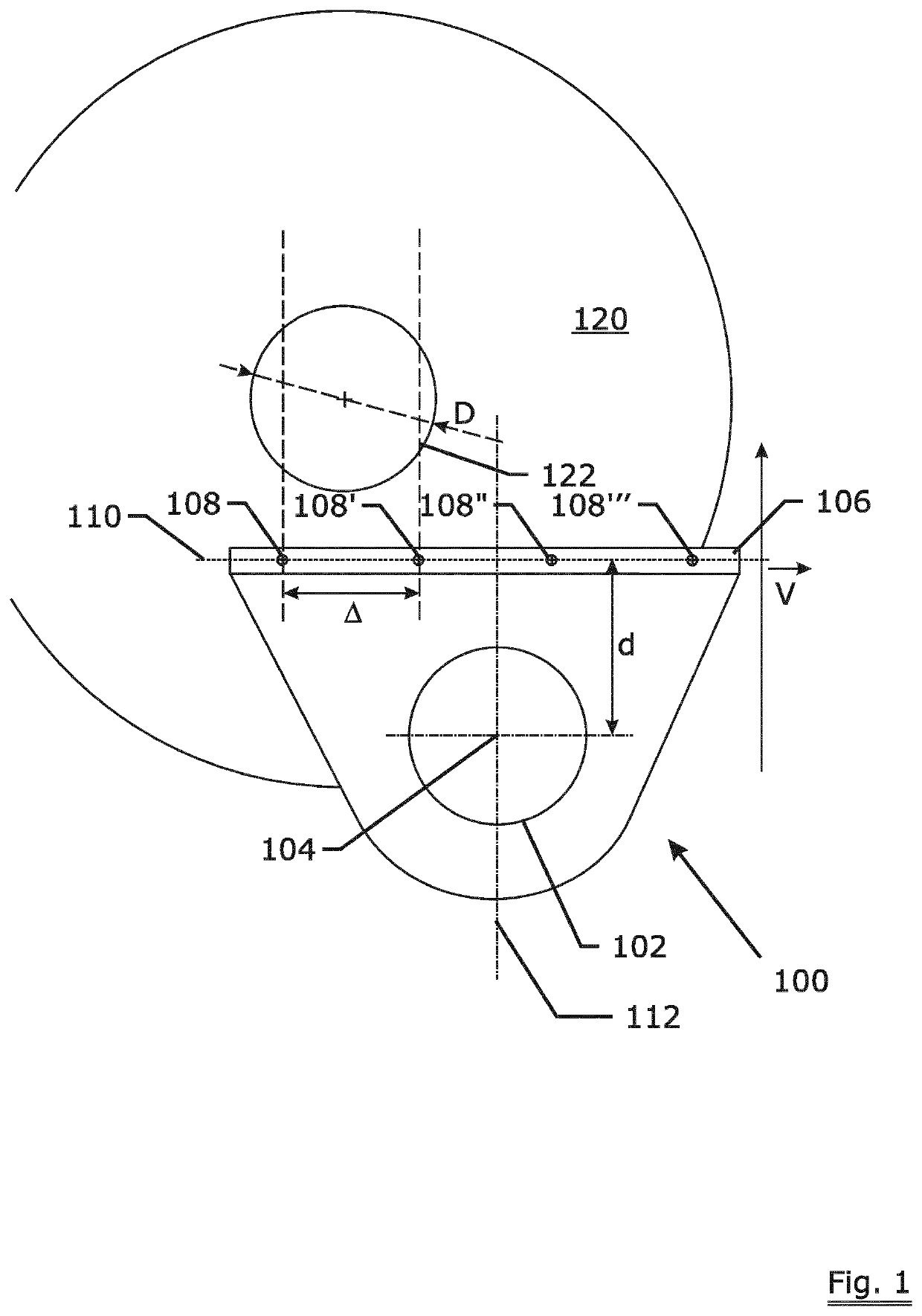
lass="d_n">[0057]FIG. 1 shows a view from above of a general embodiment of the gripper 100. The gripper comprises a driveable clamp 102 that is mounted on an arm of a robot or automatically guided vehicle or similar device (not shown). The clamp 102 has a reference axis indicated with 104 that is in this case perpendicular to the plane of the sheet. The spool to be gripped is shown as 120 and has a circular grip part 122 that is in this case the bore hole of the spool 120. The circular grip part 122 has a diameter indicated with ‘D’. The clamp size—corresponding to the diameter of the clamp 102—is thus slightly less than D in order to allow insertion of the clamp into the bore hole. The gripper has a scanning system 106 comprising four sensors indicated with 108, 108′, 108″, 108′″ on a line 110. The sensors are separated from one another by a distance ‘Δ’. The distance A is just less than D / 2 for example 0.45×D. The sensors sense the presence or absence of the spool body 120 in a di...


PUM


Abstract

The invention relates to a gripper (100) for finding, clamping and releasing spools (120) having a circular grip part (122) such as a flange or a bore hole as well as a method to operate such gripper. The gripper (100) comprises a driveable clamp (102) that is provided with a scanning system (106) comprising ‘presence-absence detectors’ (108) that detect the presence of the absence of the circular grip part (122). The gripper (100) is slowly moved over the flange of the spool and by means of the detectors (108) and some calculation the centre of the grip part (122) is identified followed by the gripping of the spool. The gripper (100) has the advantage that no back-and-forth movement is needed in order to locate the circular grip part (122).

Description

TECHNICAL FIELD[0001]The invention relates to a gripper for finding, clamping and releasing spools. The gripper enables the automated handling of spools in an industrial environment.BACKGROUND ART[0002]In the production of elongated articles such as yarns, threads, ropes, cords, steel cords and the like final and intermediate products are carried on spools. The number of times a spool is picked up to make for example one final spool of a simple steel cord construction like 7×7 easily rises above hundred as not only the full spools have to be picked up but also the empty ones have to be removed. Therefore the making of the mentioned articles to a large extent reduces to the activity of picking up, moving and placing empty and full spools. There is therefore a constant desire to reduce this number of handlings e.g. by increasing the capacity of those spools or to automate the handling in order to eliminate this tedious and labour intensive task.[0003]When automating the task of pickin...

Claims


Application Information

Patent Timeline
IPC IPC(8): B25J9/16B25J15/00B25J13/08B65H67/06
CPCB25J13/08B25J15/0047B25J9/1612B65H67/065B25J9/1694B25J15/0028B25J9/1653B65H2701/35B65H2701/31
Inventor HUGELIER, JOHAN
Owner NV BEKAERT SA
Why Eureka
Eureka Blog
Learn More