System and Apparatus for Conditioning of Indoor Air

a technology for indoor air and systems, applied in lighting and heating apparatus, space heating and ventilation control systems, heating types, etc., can solve the problems that the cold water provided by the chiller in the hvac system cannot be can not be simultaneously near the dew point of all chilled beams requiring cooling, so as to reduce the time it takes, prevent condensation, and maximize the cooling rate

Active Publication Date: 2020-11-05
CHILLED BEAM CONTROLS LLC
View PDF0 Cites 2 Cited by
  • Summary
  • Abstract
  • Description
  • Claims
  • Application Information

AI Technical Summary

Benefits of technology

[0011]Aspects of the invention relate to a control system that may be used with a single chilled beam, thus allowing each chilled beam to be independently controlled reducing the time it takes to achieve and maintain comfortable conditions in all conditioned spaces serviced by a HVAC system.
[0012]When operating in a cooling mode the water input to a chilled beam may be just above the dew point to maximize the rate

Problems solved by technology

As the dew point will depend on the ambient conditions of each chilled beam, the cold water provided by the chill

Method used


Image

  • System and Apparatus for Conditioning of Indoor Air
  • System and Apparatus for Conditioning of Indoor Air
  • System and Apparatus for Conditioning of Indoor Air

Examples


Embodiment Construction

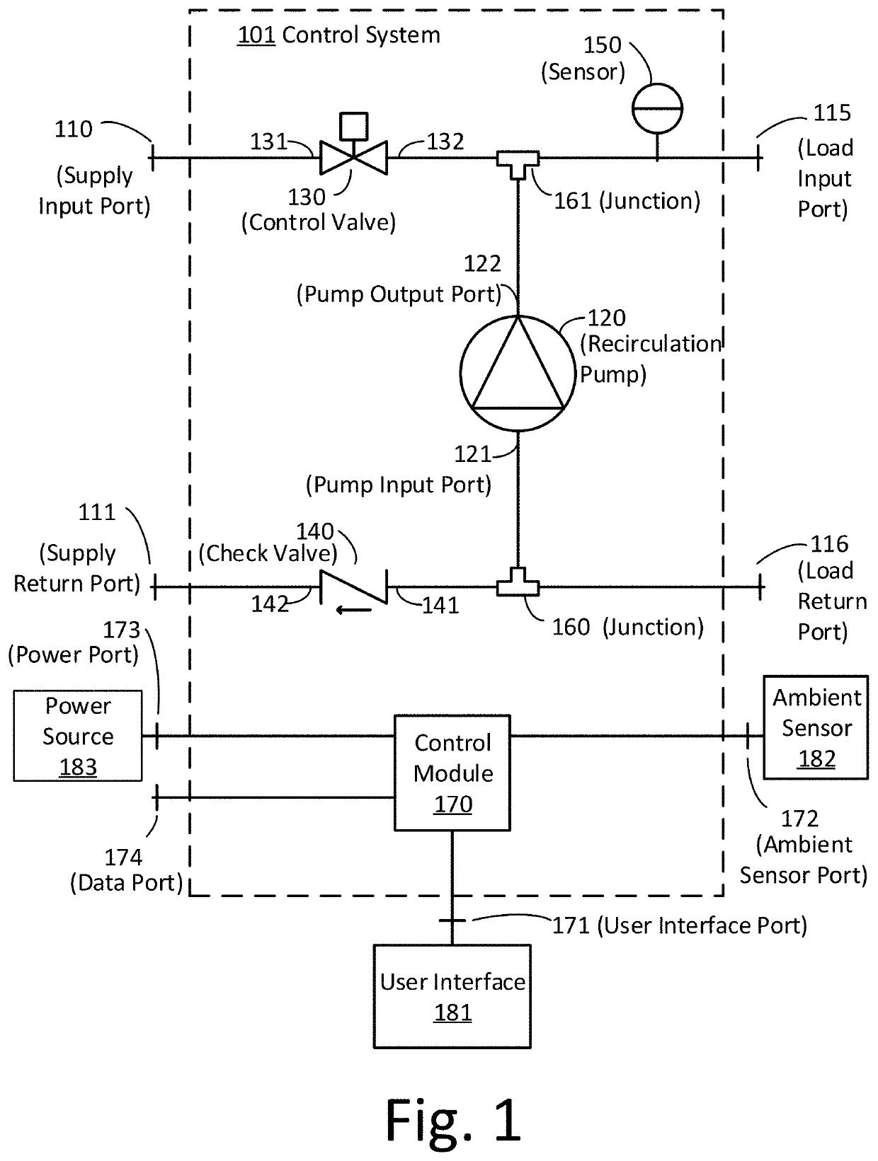
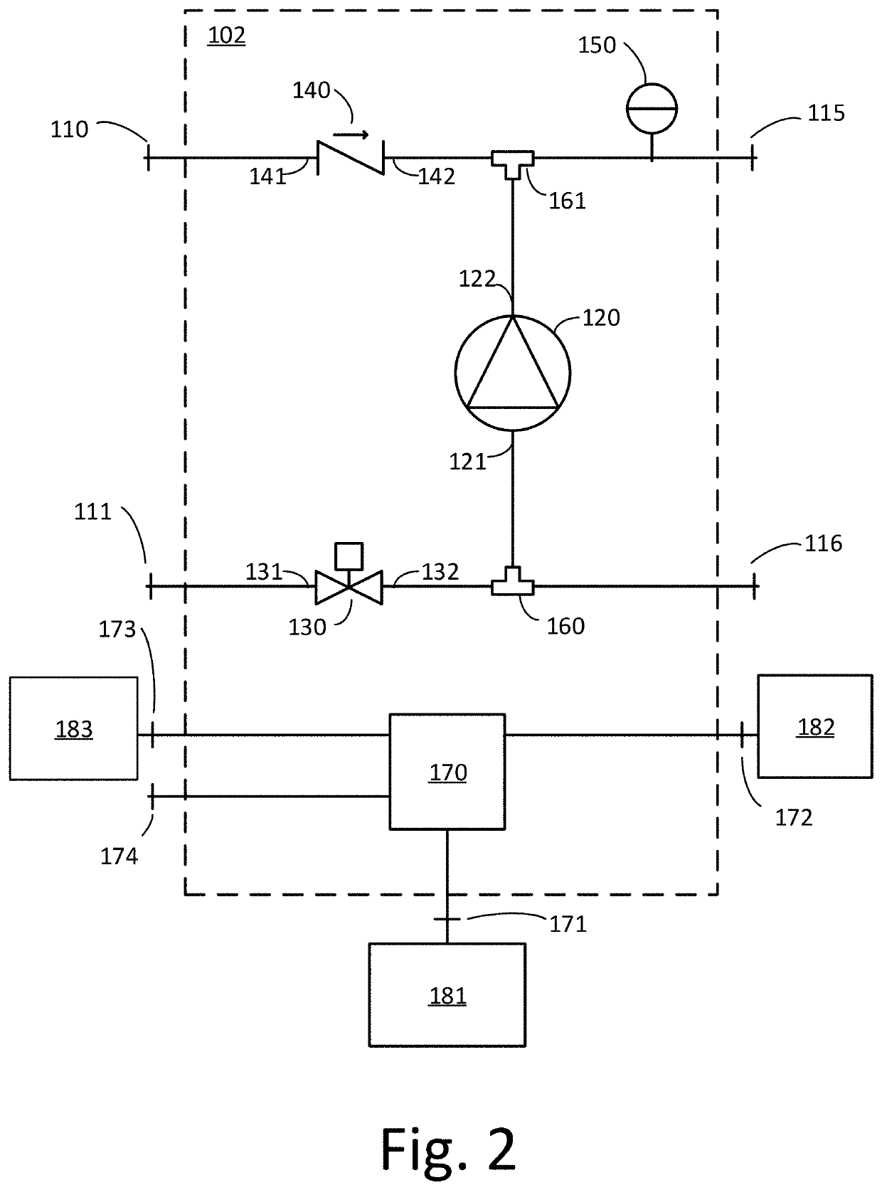
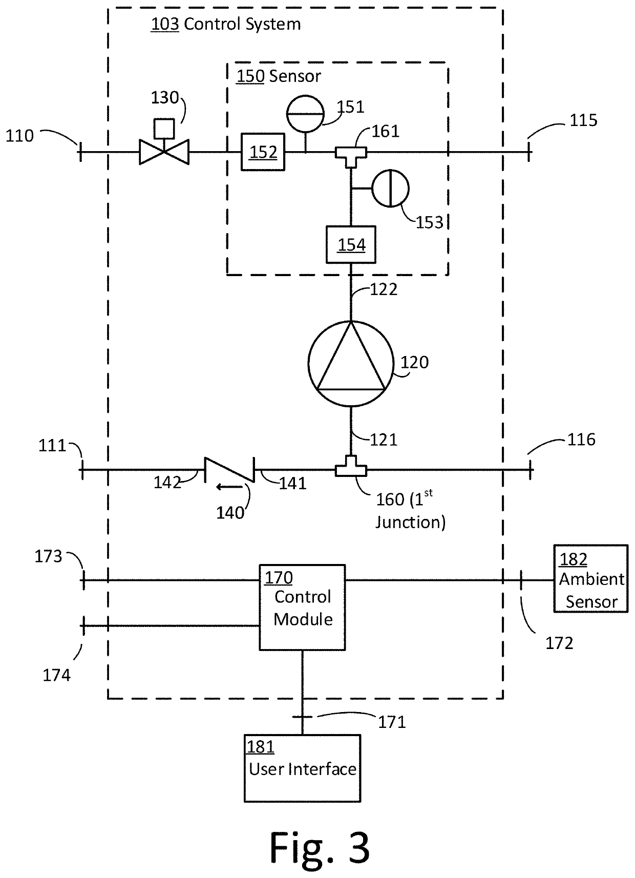
[0043]Chilled beams in combination with an ERV are starting to be used to overcome problems with conventional HVAC systems. Compared to conventional HVAC systems, a system with chilled beams and an ERV can provide much better humidity control, improved indoor air quality, significantly lower energy costs, much quieter living spaces, and reduced maintenance costs. The inventors have recognized and appreciated that a reason the chilled beams and ERV system is not being used more is because of the complicated designs and high costs for the systems that control the chilled beams. Some aspects of the disclosure relate to a control system design that will allow chilled beam and ERV systems to be more economically viable.

[0044]The inventors have recognized and appreciated the difficulties in adapting chilled beam system designs for each new installation (e.g., in a building or other facility to have conditioned air). Particularly existing chilled beam control systems can require large, exp...


PUM


Abstract

A control system is provided for controlling heating and/or cooling with a conditioning load such as fan coils and chilled beams. Based on user input and ambient conditions, the control system determines a desired temperature for the liquid entering the load and combines fresh supply liquid (e.g., from a chiller or boiler) with a portion of the liquid that has passed through the load, to achieve the target load input temperature for the liquid. A recirculation pump may be used to return a portion of the liquid exiting the load for mixing with the fresh supply liquid and a control valve may be used to adjust the ratio of fresh supply liquid and recirculated liquid to achieve the targeted temperature. The control systems can be compatible with a variety of liquid supply systems such as two- and four-pipe systems.

Description

RELATED APPLICATION[0001]The present application claims priority under 35 U.S.C. § 119(e) to U.S. provisional patent application, U.S. Ser. No. 62 / 843,514, filed May 5, 2019, which is herein incorporated by reference in its entirety.TECHNICAL FIELD[0002]The present disclosure relates to the field of conditioning of indoor air. Some aspects of the disclosure relate to control systems for chilled beams.BACKGROUND[0003]Heating, ventilation, and air conditioning (HVAC) technologies have been developed for conditioning indoor air with the goal of effectively and efficiently providing comfort for occupants and / or satisfactory ambient conditions for property. Chilled beams are a heating and cooling technology that can utilize heated or chilled water to condition indoor air. Water is passed through a finned-tube coil of pipe which exchanges heat with the surrounding air through radiation and convection. A chilled beam may be mounted to the ceiling of a room.[0004]There are two types of chil...

Claims


Application Information

Patent Timeline
IPC IPC(8): F24F11/84F24F11/47
CPCF24F11/47F24F2110/10F24F2110/20F24F11/84F24F2140/20F24D3/165F24H15/32F24H15/335F24H15/254F24H15/414
Inventor FURMAN, RICHARDTHOMAS, ZACHARY M.
Owner CHILLED BEAM CONTROLS LLC
Why Eureka
Try Eureka