Steering system

Active Publication Date: 2020-11-19
JTEKT CORP
View PDF4 Cites 2 Cited by
  • Summary
  • Abstract
  • Description
  • Claims
  • Application Information

AI Technical Summary

Benefits of technology

[0008]With the steering system of the aspect, it is p

Problems solved by technology

Thus, steered angle estimation accuracy decreases due to backlash etc. caused by clearances (looseness) among the output gear, the input gear, the ball nut, and the balls.
In particular, if there is an er

Method used


Image

  • Steering system
  • Steering system
  • Steering system

Examples


Example

[0020]A first embodiment of the disclosure will be described with reference to the accompanying drawings. Embodiments described below are represented as specific examples suitable for carrying out the disclosure. Although some parts exemplify various technical matters that are technically preferable, the technical scope of the disclosure is not limited to the specific examples.

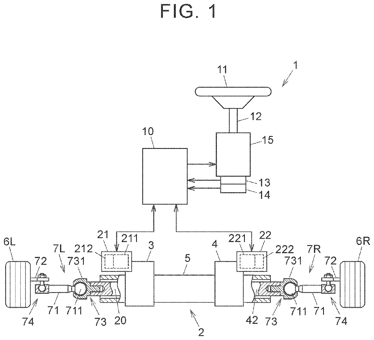
[0021]FIG. 1 is a schematic diagram showing an example of a schematic configuration of a steer-by-wire steering system according to a first embodiment of the disclosure. In the following description, terms “right” and “left” refer to right and left sides in a width direction of a vehicle in which the steering system is mounted.

[0022]The steering system 1 includes a steering wheel 11, a steering shaft 12, a steering angle sensor 13, a torque sensor 14, a reaction actuator 15, a steering operation device 2, and a control device 10. The steering wheel 11 serves as a steering member operated by a driver. The steer...

Example

Second Embodiment

[0061]Next, a second embodiment of the disclosure will be described with reference to FIGS. 6A to 6C. The present embodiment is different from the first embodiment in that a rotary shaft 90 is supported by the housing 5 so as to rotate with movement of the rack shaft 20 in the axial direction and a position detection sensor 9 attached to the housing 5 for detecting the axial position of the rack shaft 20 detects a rotation angle of the rotary shaft 90.

[0062]FIG. 6A is a sectional view showing the position detection sensor 9 and the rotary shaft 90 according to the second embodiment of the disclosure. FIG. 6B is a sectional view showing a meshing portion between the rotary shaft 90 and the rack shaft 20. FIG. 6C is a configuration diagram showing a configuration example of the position detection sensor 9.

[0063]The rotary shaft 90 has a first end portion in the axial direction held by the position detection sensor 9 and a second end portion in the axial direction supp...


PUM


Abstract

A steering system includes a housing, a steering operation shaft that is housed in the housing and configured to move in an axial direction to steer right and left steered wheels, a first drive source that generates a first drive force, a second drive source that generates a second drive force, a first power transfer unit that applies an axial force to the steering operation shaft with the first drive source, a second power transfer unit that applies an axial force to the steering operation shaft with the second drive force, a position detection sensor that is provided in the housing and detects an axial position of the steering operation shaft, and a control device that controls the first drive source and the second drive source using a detection result of the position detection sensor.

Description

CROSS-REFERENCE TO RELATED APPLICATION[0001]This application claims priority to Japanese Patent Application No. 2019-092359 filed on May 15, 2019, incorporated herein by reference in its entirety.BACKGROUND1. Technical Field[0002]The disclosure relates to a steering system.2. Description of Related Art[0003]Conventionally, there is a known steer-by-wire steering system in which a steering wheel operated by a driver and a steering operation shaft that steers right and left steered wheels are not mechanically coupled. In such a steering system, a steering gear ratio that is a ratio of a steered amount of the steered wheels with respect to an operation amount of the steering wheel can be varied based on vehicle state information such as a vehicle speed sensor and a detected value of an acceleration sensor. For example, at the time of parking a vehicle, the steering gear ratio is increased to reduce the operation amount of the steering wheel, thereby reducing a burden on a driver.[0004]...

Claims


Application Information

Patent Timeline
IPC IPC(8): B62D5/04B62D15/02
CPCB62D15/0235B62D5/0445B62D5/046B62D5/04B62D5/0403B62D5/0481B62D15/021B62D3/02B62D5/001B62D5/0424B62D5/0448B62D15/0225B62D15/0245
Inventor NAKAMURA, KEISHIKONDO, YOSHIOOGATA, TOSHIAKIKISHIDA, FUMIO
Owner JTEKT CORP
Why Eureka
Try Eureka