Device and method for improved testing of a hydraulic part for a turbomachine

a turbomachine and hydraulic part technology, applied in the direction of positive displacement liquid engine, liquid fuel engine, instruments, etc., can solve the problems of reducing the performance of the pump, the capacity of the attachment of the pump, for example the low-pressure pump, and no longer allowing the pump to operate, so as to achieve the effect of reducing the pressur

Active Publication Date: 2020-11-19
SN DETUDE & DE CONSTR DE MOTEURS DAVIATION S N E C M A
View PDF3 Cites 0 Cited by
  • Summary
  • Abstract
  • Description
  • Claims
  • Application Information

AI Technical Summary

Benefits of technology

[0019]It is thus possible to evaluate the performances of a kinetic pump, and to evaluate its attachment capacity by taking into account the aeration of the fluid, while dispensing with tests carried out with kerosene, these can be long and costly. It is also possible to dimension an inductor from the beginning of a program, without iteration on partial bench with kerosene. Furthermore, the tested fluid / gas mixtures are preferably non-flammable, unlike kerosene, thus improving the safety conditions under which the tests are carried out.
[0045]In some embodiments, the pressure in the loop is decreased through the vacuum pump. The pressure decrease is preferably gradual. It is thus possible to accurately observe the pressure values from which the stall of the kinetic pump occurs.

Problems solved by technology

It can generate vibrations, noises and flow rate instabilities that decrease the performances of the pump.
In case of appearance of the cavitation phenomenon, in the event of a pressure drop, the capacity of attachment of a pump, for example a low-pressure pump, is a fundamental issue, since it affects the operation of the engine in the event of a failure of the pump of the aircraft.
The aerodynamic stall no longer allows the pump to push the gases in the right direction, and the “high-pressure” portion of the pump (at the outlet) is no longer properly supplied by the “low-pressure” portion (at the inlet).
Currently, there is no internal model or bibliographic study reliably estimating the minimum pressure achievable before the stall of the pump occurs.
However, the current design methods do not take into account very well this major parameter and do not allow predicting the minimum achievable pressure.
There is no reliable model for estimating the minimum pressure to which a fuel inductor can “attach”.

Method used


Image

  • Device and method for improved testing of a hydraulic part for a turbomachine
  • Device and method for improved testing of a hydraulic part for a turbomachine

Examples


Embodiment Construction

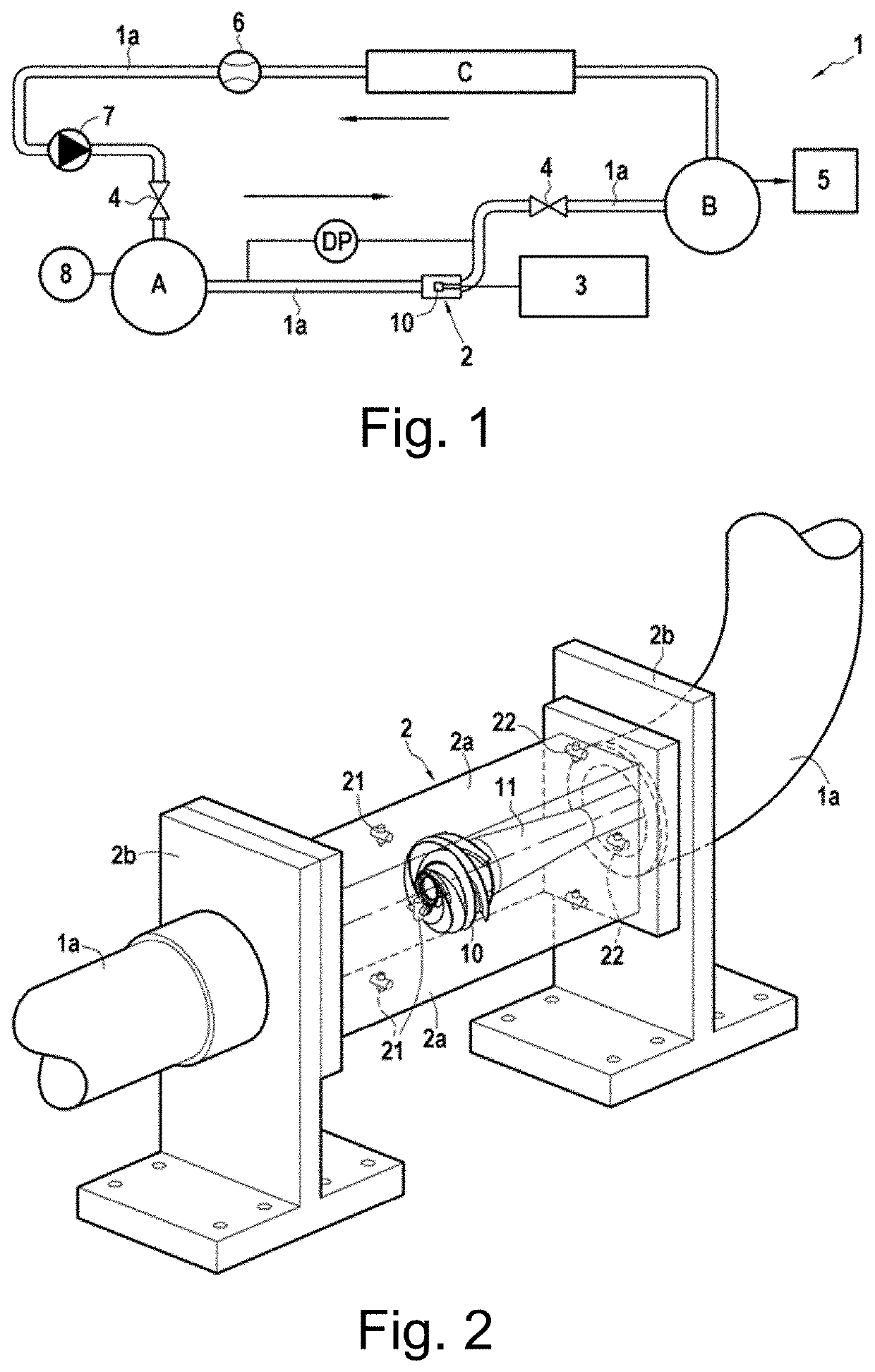
[0050]In the following description, the terms “upstream” and “downstream” are considered according to the direction of flow of the fluid in the loop, represented by the black arrows in FIG. 1.

[0051]FIG. 1 schematically represents a test device 1 for testing a hydraulic part, for example a fuel pump. In the embodiment described below, the tested hydraulic part is an inductor 10. The test device 1 is used to characterize the inductor 10 in a cavitating and non-cavitating mode. It comprises a duct 1a of circular section of 80 mm in diameter, for example, forming a closed loop in which a fluid can circulate.

[0052]The inductor 10 is disposed in a test section 2 and is driven by a motor 3 via a shaft 11, and can reach rotational speeds of up to 9,000 rpm, the assembly being adaptable according to the tested device. The rotational speed of the inductor is measured with a speed measuring means (not represented).

[0053]The flow rate Q of the flow can be measured by a flow meter 6 disposed bet...


PUM

PropertyMeasurementUnit
pressureaaaaaaaaaa
pressureaaaaaaaaaa
atmospheric pressureaaaaaaaaaa

Abstract

Device (1) for testing a hydraulic part (10) for a turbomachine, the device comprising a closed loop for circulation of a working fluid, the loop comprising at least one recirculation pump (7) configured to circulate the working fluid in the loop according to a direction of circulation, at least one valve (4) for regulating the flow rate of a working fluid, at least one reservoir (A) configured to store the working fluid, a test section (2) configured to accommodate the hydraulic part (10), the device (1) further comprising a gas injection means (8) configured to inject and dissolve, at atmospheric pressure, a gas in the working fluid stored in the reservoir (A).

Description

CROSS-REFERENCE TO RELATED APPLICATIONS[0001]This disclosure claims priority to French Patent Application No. 1905134, filed on May 16, 2019, which is hereby incorporated by reference in its entirety.TECHNICAL FIELD[0002]This present disclosure relates to the field of fuel pumps of aeronautical turbomachines, in particular a device for testing a fuel pump of a turbomachine, and a method for testing a fuel pump using such a device.INTRODUCTION[0003]The inductor of a fuel pump aims at lowering the minimum acceptable inlet pressure to ensure the proper operation of the fuel pump. The inductors are generally placed upstream on the same drive shaft as the wheel in the centrifugal pumps. Their goal is in particular to prevent the phenomenon of cavitation and reduce the Net positive suction head (NPSH) required for a pump to work properly.[0004]The cavitation phenomenon occurs when the pressure of the liquid drops below the vapor pressure of the liquid. It can generate vibrations, noises a...

Claims


Application Information

Patent Timeline
Patent Type & Authority Applications(United States)
IPC IPC(8): G01L13/00F04D29/18
CPCF05B2260/83G01L13/00F04D29/18F04B51/00F04D15/0088
Inventor PORA, LOÏCTOMOV, PETARMAGNE, THÉODORE
Owner SN DETUDE & DE CONSTR DE MOTEURS DAVIATION S N E C M A
Why Eureka
Try Eureka