

Liquid Discharge Head
- Summary
- Abstract
- Description
- Claims
- Application Information
AI Technical Summary
Benefits of technology
Problems solved by technology
Method used
Image

Examples
first embodiment
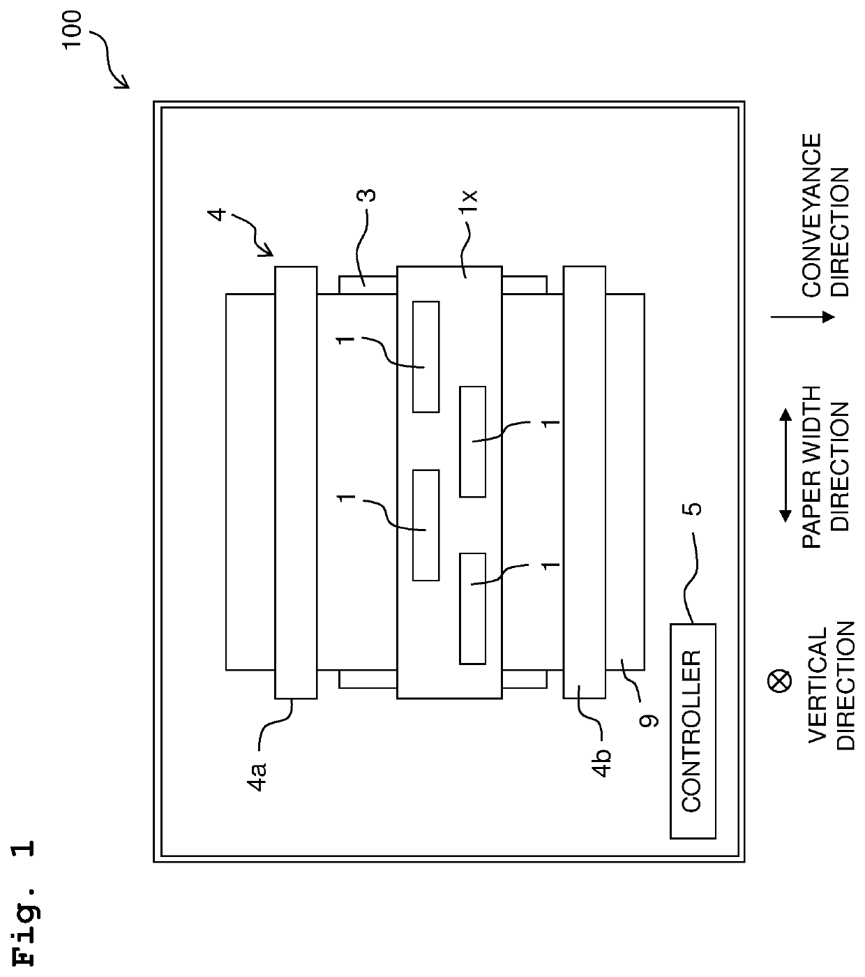
[0016]Firstly, the overall configuration of a printer 100 provided with a head 1 according to a first embodiment of the present disclosure will be explained, with reference to FIG. 1.
[0017]The printer 100 is provided with a head unit 1x including four heads 1, a platen 3, a conveyor 4 and a controller 5.
[0018]A paper sheet (sheet, paper) 9 is placed on the upper surface of the platen 3.
[0019]The conveyor 4 has two roller pairs 4a and 4b which are arranged with the platen 3 intervened therebetween in a conveyance direction. In a case that a conveying motor (of which illustration is omitted in the drawings) is driven by control of the controller 5, the roller pairs 4a and 4b rotate in a state that the paper sheet 9 is sandwiched or pinched therebetween, thereby conveying the paper sheet 9 in the conveyance direction.
[0020]The head unit 1x is elongated in a paper width direction (direction orthogonal to both of the conveyance direction and the vertical direction), and is of a line syst...
second embodiment
[0059]Next, a head 201 according to a second embodiment of the present disclosure will be explained, with reference to FIG. 5.
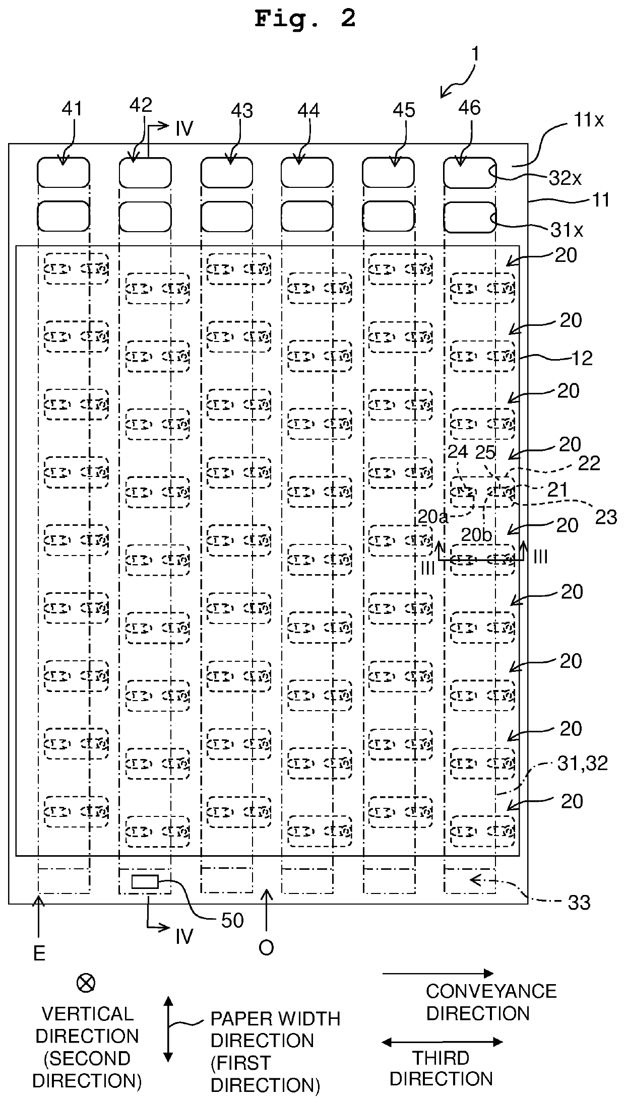
[0060]In the first embodiment (FIG. 2), the temperature sensor 50 is provided on the channel set 42 (the channel set which is positioned most closely to the middle point, in the third direction, between the center O in the third direction of the arrangement area of the six channel sets 41 to 46 and the end E in the third direction of the arrangement area). In the second embodiment (FIG. 5), however, a temperature sensor 50 is provided on the channel set 43 (the channel set which is positioned most closely, in the third direction, to the center 0 in the third direction of the arrangement area of the six channel sets 41 to 46).
[0061]According to the second embodiment wherein although the position of the temperature sensor 50 is different from that in the first embodiment, the second embodiment satisfies the requirement similar to that in the first embodiment, t...
third embodiment
[0063]Next, a head 301 according to a third embodiment of the present disclosure will be explained, with reference to FIG. 6.
[0064]In the first embodiment (FIG. 2), the temperature sensor 50 is provided on the channel set 42 (the channel set which is positioned most closely to the middle point, in the third direction, between the center O in the third direction of the arrangement area of the six channel sets 41 to 46 and the end E in the third direction of the arrangement area). In the third embodiment (FIG. 6), however, temperature sensors 50 are provided on the six channel sets 41 to 46, respectively.
[0065]According to the third embodiment wherein although the position of the temperature sensor 50 is different from that in the first embodiment, the third embodiment satisfies the requirement similar to that in the first embodiment, thereby achieving the effects similar to those in the first embodiment.
[0066]Further, in the third embodiment, since the temperature sensors 50 are prov...
PUM
 Abstract
Description
Claims
Application Information