
Power feeding device and power receiving device for contactless power transmission

Active Publication Date: 2016-03-03
MURATA MFG CO LTD
View PDF0 Cites 6 Cited by
  • Summary
  • Abstract
  • Description
  • Claims
  • Application Information

AI Technical Summary

Benefits of technology

The present invention provides a device that can accurately detect the temperature of an object on a cover. This is achieved by measuring the distance between the surface of the cover and the temperature-sensitive detector. By maintaining the proper distance, the device can accurately detect the temperature of the object on the cover.

Problems solved by technology

However, the power feeding device, etc. has a problem that, depending on the position of the temperature-sensitive sensor, when an object is placed on the cover, the temperature of the object may be unable to be accurately detected.

Method used


Image

  • Power feeding device and power receiving device for contactless power transmission
  • Power feeding device and power receiving device for contactless power transmission
  • Power feeding device and power receiving device for contactless power transmission

Examples


first example

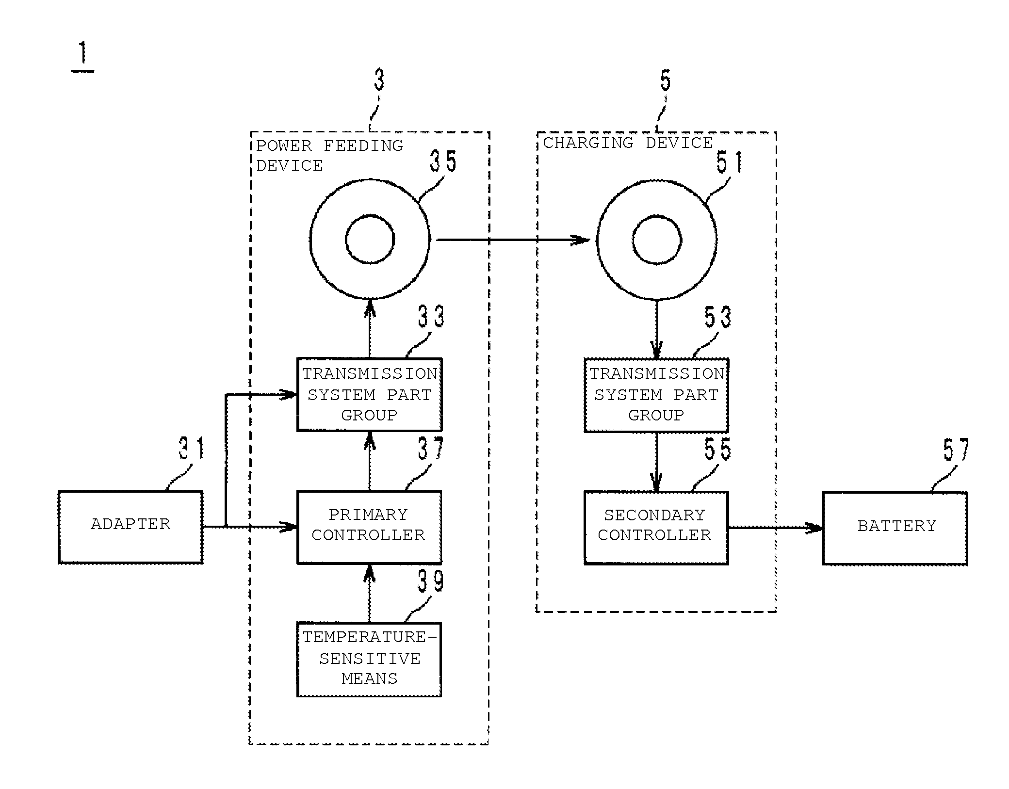
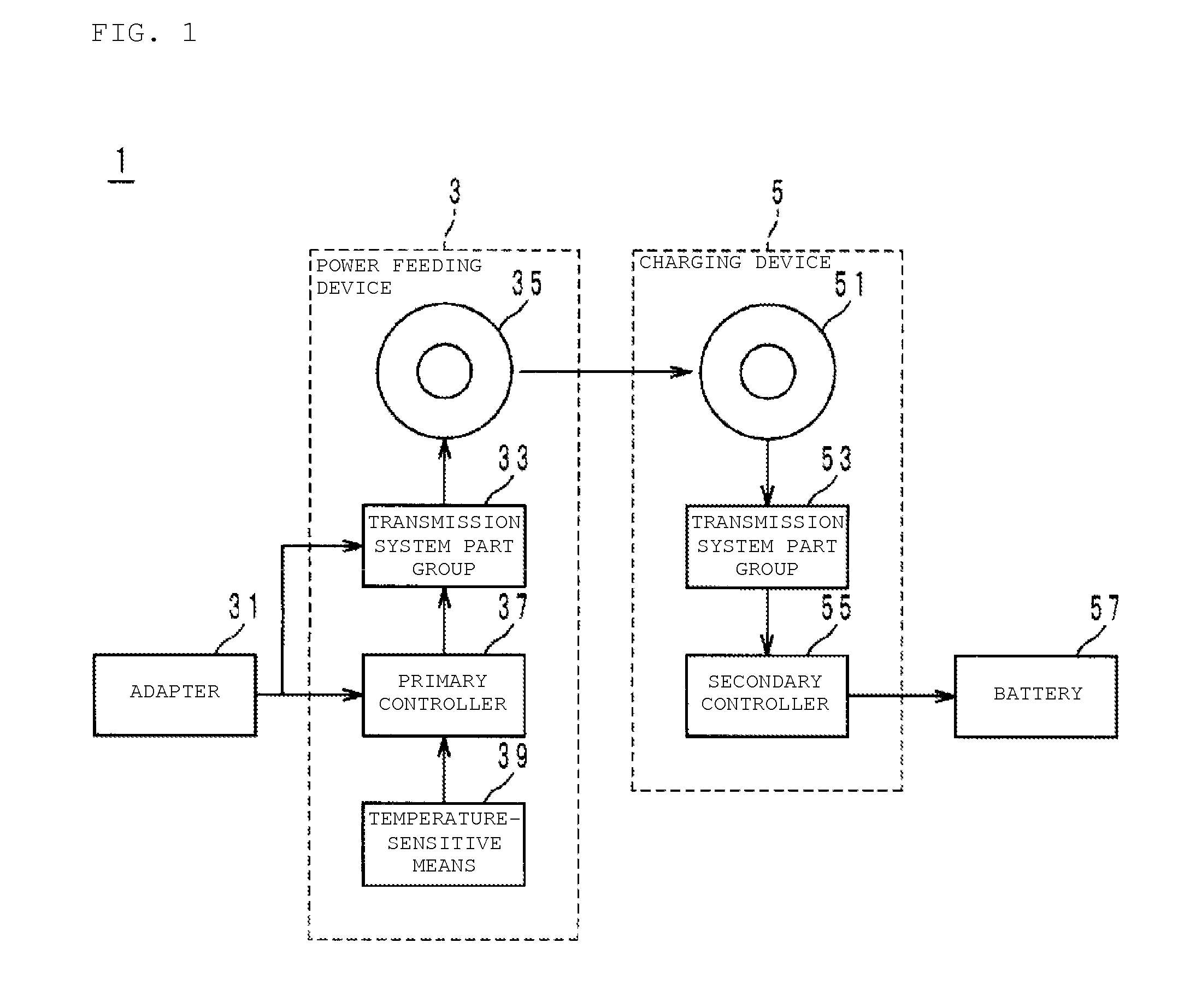
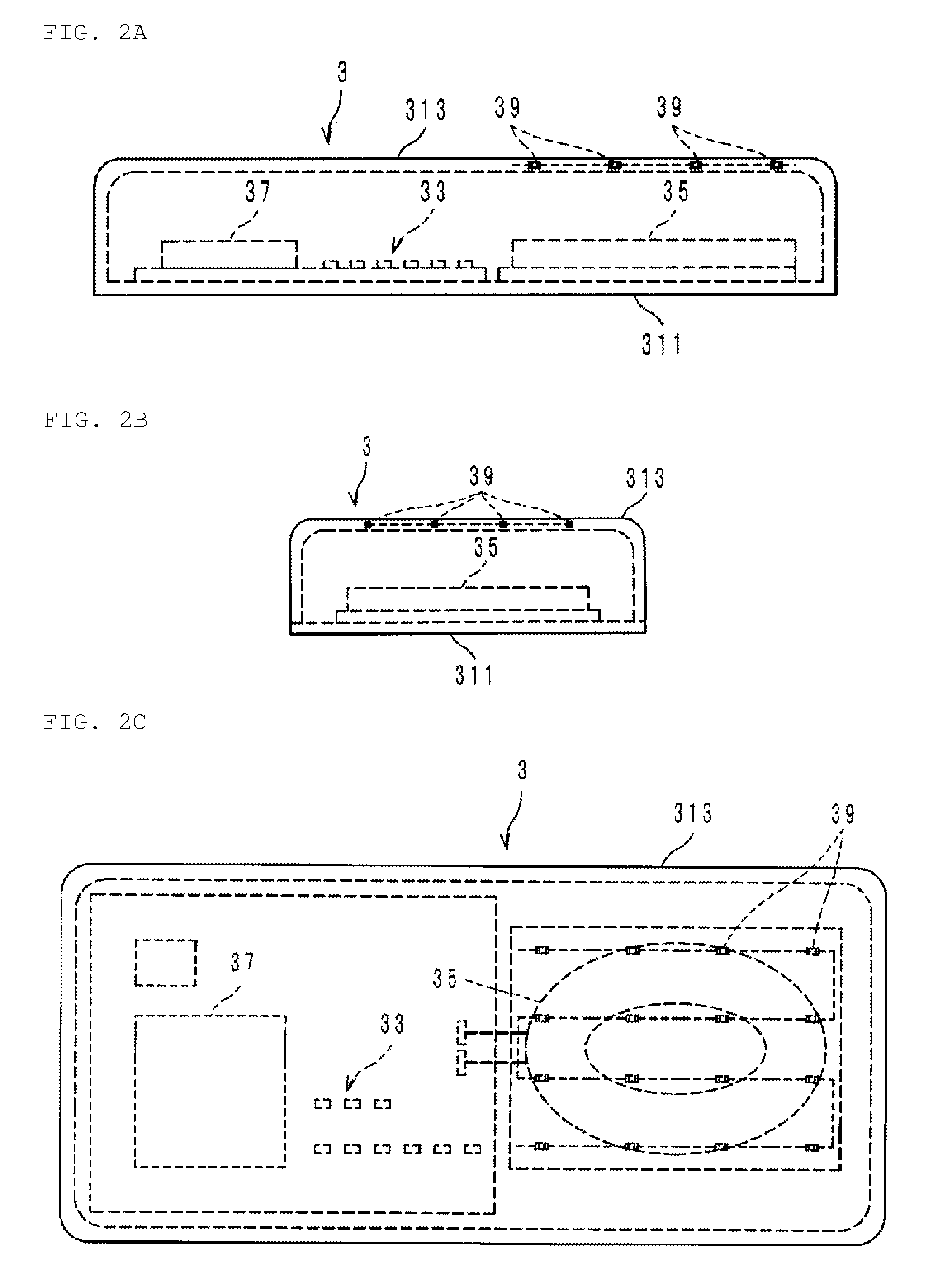
[0027]The object to be detected is an aluminum piece of about 5 [cm] square. In addition, the material of the cover 313 is an epoxy resin with a thermal conductivity λ of about 0.25 [W / (m·K)]. When the aluminum piece was put on the cover 313, the temperature T0 of the aluminum piece was increased to about 150 [° C.] under a calm condition at about 25 [° C.]. When safety, etc. of the power feeding device 3 are taken into account, the temperature-sensitive detector 39 desirably detects the existence of the aluminum piece at the temperature T1 of, for example, about 130 [° C.] (temperature difference (T0−T1): about 20° C.). In this case, the power feeding device 3 is designed so that the distance L is about 0.00248 [m] or less. It is to be noted that T0 and T1 are substituted in terms of absolute temperature in the equation (1), while T0 and T1 are referred in terms of degrees C., not in terms of absolute temperature, in the text and table from the perspective of ease of understanding....

second example

[0031]The inventor further prepared, for the material of the cover 313, glass with a thermal conductivity λ of about 0.17 [W / (m·K)], instead of the epoxy resin. Also in this case, when an aluminum piece of about 5 [cm] square is regarded as an object to be detected in the same manner as described above, T0 will be 150 [° C.]. In addition, when the temperature T1 is set to about 130 [° C.] (temperature difference (T0−T1): about 20° C.), the distance L is about 0.00169 [m] or less from the equation (1).

[0032]The inventor of the present application prepared, with the six distances L shown in Table 2 below, circuits with type 1005 NTC thermistors buried as the temperature-sensitive detector 39 in the cover 313 made of the glass (referred to as evaluation samples No. 7 to No. 12 in Table 2). In regard to the sample No. 7, the distance L was made to be about 10 [mm], and the distance L of the sample No. 8 was made to be about 5 [mm]. In regard to the samples Nos. 9 to 12, the distance L i...


PUM


Abstract

A power feeding device includes a cover, a primary coil covered with the cover and provided in a predetermined direction with respect to the cover, and a temperature-sensitive detector that detects the temperature of an object on the cover. When the distance from the surface of the cover to the temperature-sensitive detector in the predetermined direction is denoted by L [m], the temperature of the object to be subjected to thermometry by the temperature-sensitive detector is denoted by T0[K], the temperature to be detected by the temperature-sensitive detector is denoted by T1[K], and the thermal conductivity of the cover is denoted by λ [W / (m·K)], L satisfies the following equationL≤λ×(T0-T1)5×T1.(1)This allows the temperature of the object on the cover to be accurately detected.

Description

BACKGROUND OF THE INVENTION[0001]1. Field of the Invention[0002]The present invention relates to a power feeding device and a power receiving device that transmit and receive power to and from a device in a contactless manner.[0003]2. Description of the Related Art[0004]Conventionally, examples of this type of power feeding device and power receiving device include, for example, devices as described in Japanese Patent Application Laid-Open No. 2013-017247. This power feeding device includes a primary coil that generates a magnetic flux when an alternating current flows, a cover that covers the primary coil, and a sheet-like temperature-sensitive sensor that detects the temperature of an object (foreign object or power receiving device) on the cover. Thus, during power transmission, the temperature-sensitive sensor is used to detect a temperature increase on the cover, thereby detecting the presence of the object on the cover.[0005]In the power feeding device, the coil is disposed on...

Claims


Application Information

Patent Timeline
IPC IPC(8): H02J5/00G01K7/22G01K13/00
CPCH02J17/00G01K7/22G01K13/00G01K1/026H02J5/005H02J50/10H02J50/60H02J7/35H02J50/005H02J50/12
Inventor IBARAGI, HIROSHI
Owner MURATA MFG CO LTD
Learn More