Treatment force application device

a technology of force application and force, which is applied in the field of manual therapy equipment, can solve the problems of inconsistent force levels, depth, angle of entry, duration,

Inactive Publication Date: 2020-12-17
RIVERON RUDY ALEXANDER
View PDF7 Cites 0 Cited by
  • Summary
  • Abstract
  • Description
  • Claims
  • Application Information

AI Technical Summary

Benefits of technology

[0014]In preferred embodiments, a treatment force application device includes a proximal end having a weight and having a support for a practitioner; a distal end having a treatment interface configured for applying a therapeutic treatment including at least a treatment force; and a connection between the support and the treatment interface; wherein the connection is lockably adjustable by the practitioner to establish a placement of the treatment interface relative to the support; and the weight is sufficient to substantially prevent movement of the treatment interface relative to the support when the connection is locked.
[0015]As an example, in certain embodiments a t

Problems solved by technology

Further, although forms of therapeutic touch and force application have been present throughout history and cultures, practitioners have lacked a means for both defining and providing said force in both an easy and reproducible manner.
Additionally, as forces are typically applied using no other sensor than the human brain, quantifying these forces has been limited.
Current methods of force application to biological tissue, largely the human body, rely primarily on effortful actions of another human body, creating wear and tear on the applicator while inevitably resulting in inconsistent levels of force, depth, angles of entry, and duration.
Current devices used to mitigate damage to the human force applicator's natural appendages still require the practitioner to engage with the devices by gripping and bracing skeletal muscle to create

Method used


Image

  • Treatment force application device
  • Treatment force application device
  • Treatment force application device

Examples


Embodiment Construction

[0098]Following are more detailed descriptions of various related concepts related to, and embodiments of, methods and apparatus according to the present disclosure. It should be appreciated that various aspects of the subject matter introduced above and discussed in greater detail below may be implemented in any of numerous ways, as the subject matter is not limited to any particular manner of implementation. Examples of specific implementations and applications are provided primarily for illustrative purposes.

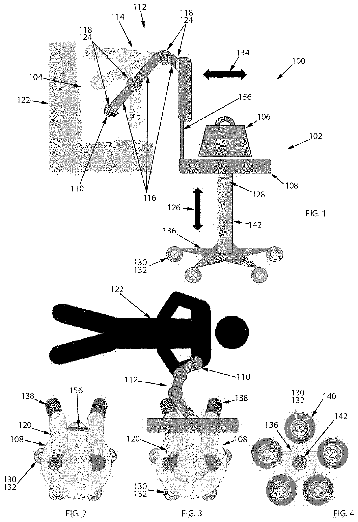
[0099]The invention provides, in preferred embodiments, a treatment force application device or instrument.

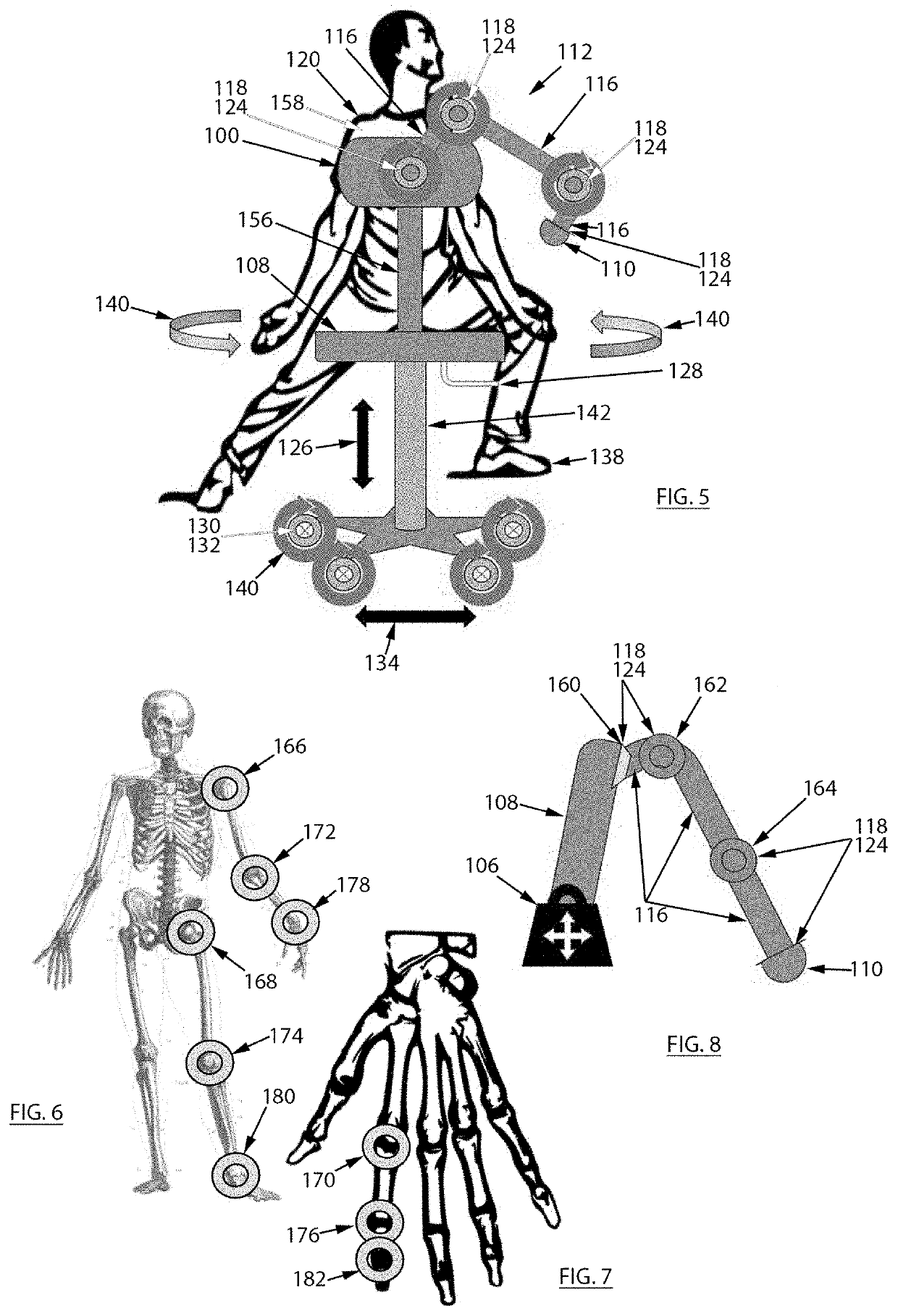
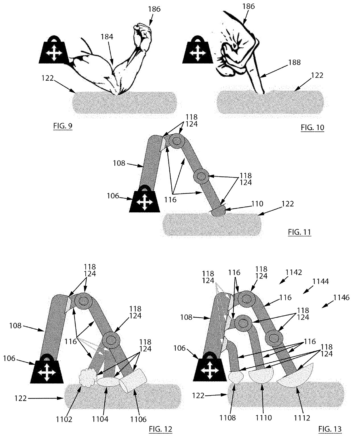
[0100]Referring now to FIGS. 1-5, a treatment force application device 100 of a preferred embodiment of the invention is illustrated. The device 100 has a proximal end 102 and a distal end 104. The proximal end 102 has a weight 106 and a support 108 for a practitioner 120. The distal end 104 has a treatment interface 110 configured for applying a therapeutic treatment in...


PUM


Abstract

A treatment force application device preferably for use on biological tissue includes a proximal end having a weight and having a support for a practitioner; a distal end having a treatment interface configured for applying a therapeutic treatment including at least a treatment force; and a connection between the support and the treatment interface. The connection is lockably adjustable by the practitioner to establish a placement of the treatment interface relative to the support. The weight is sufficient to substantially prevent movement of the treatment interface relative to the support when the connection is locked. The support enables movement of the practitioner to provide a practitioner force, and the practitioner force is transferred from the support to the treatment interface through the connection. The support includes at least one flexible brace against which the practitioner can press to provide the practitioner force. The therapeutic treatment further includes at least one of heat, cold, moisture, vibration, pulsing, ultrasound, radiation, chemicals, and medicine. The treatment interface can be configured for obtaining biometric, treatment, physical, mechanical, force and environmental data related to use of the device.

Description

FIELD OF THE INVENTION[0001]The invention relates generally to manual therapy equipment, and specifically to a treatment force application device.CROSS REFERENCE TO RELATED APPLICATIONS[0002]The present application claims priority from the following U.S. Provisional Application, the entire disclosure of which, including but not limited to any and all cited references, is incorporated herein by reference: U.S. Provisional Application No. 62 / 862,108 (filed Jun. 16, 2019).BACKGROUND OF THE INVENTION[0003]Manual therapy has existed for thousands of years as the intentional manipulation of body tissues for the relief of pain, discomfort, and other ailments that may affect living creatures in a myriad of criterion from purely physical to mental, emotional, spiritual and others. It may even predate the human species as animals have been observed utilizing surfaces in the wild to provide themselves with pressure to various bodily surface areas.[0004]Its acceptance in the West as a medical i...

Claims


Application Information

Patent Timeline
IPC IPC(8): A61H1/00A61H23/04
CPCA61H23/04A61H2201/0149A61H1/008A61H2201/1666A61H2201/0173A61H2201/0207A61H2201/0157A61H2201/5058A61H2201/0214A61H2201/10A61H2201/1671A61H23/00
Inventor RIVERON, RUDY ALEXANDER
Owner RIVERON RUDY ALEXANDER
Why Eureka
Try Eureka