

Combustion chamber structure of engine
Active Publication Date: 2020-12-17
MAZDA MOTOR CORP
View PDF0 Cites 1 Cited by
- Summary
- Abstract
- Description
- Claims
- Application Information
AI Technical Summary
Benefits of technology
[0005]An object of the present invention is to provide an engine combustion chamber structure having a cavity in a crown face of a piston to cr
Problems solved by technology
Although the cavity provided in the crown face of the piston contributes to creating suitable combustion, the ideal combustion is currently still not achieved.
For example, the cavity structure disclosed in Pa
Method used
View moreImage
Smart ImageViewing Examples

Examples
 PUM
 Abstract
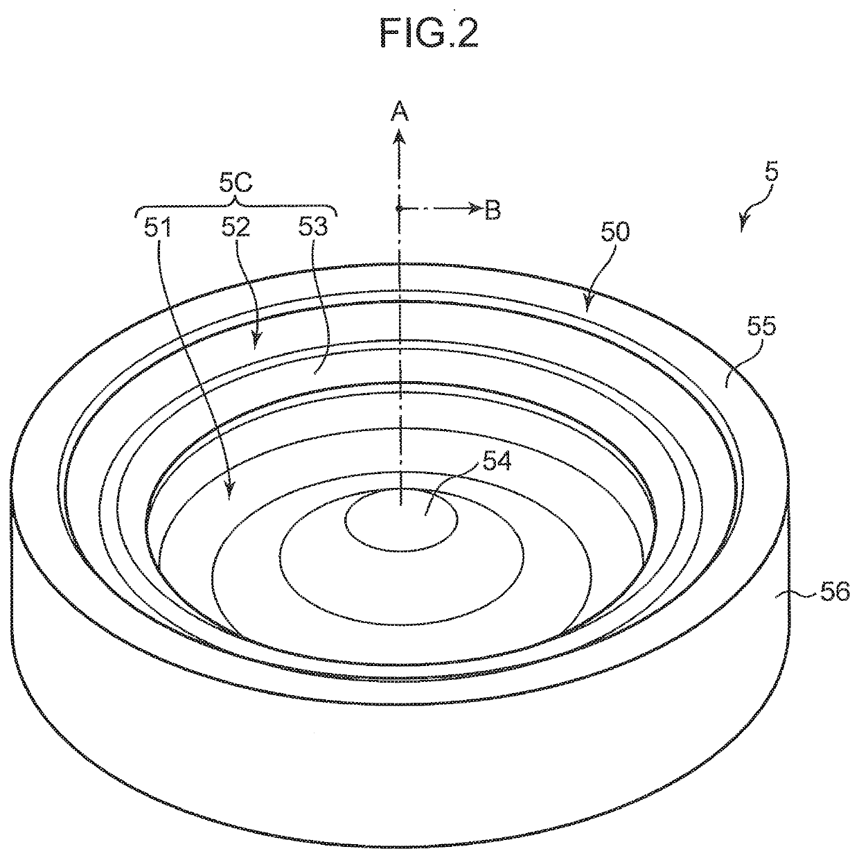
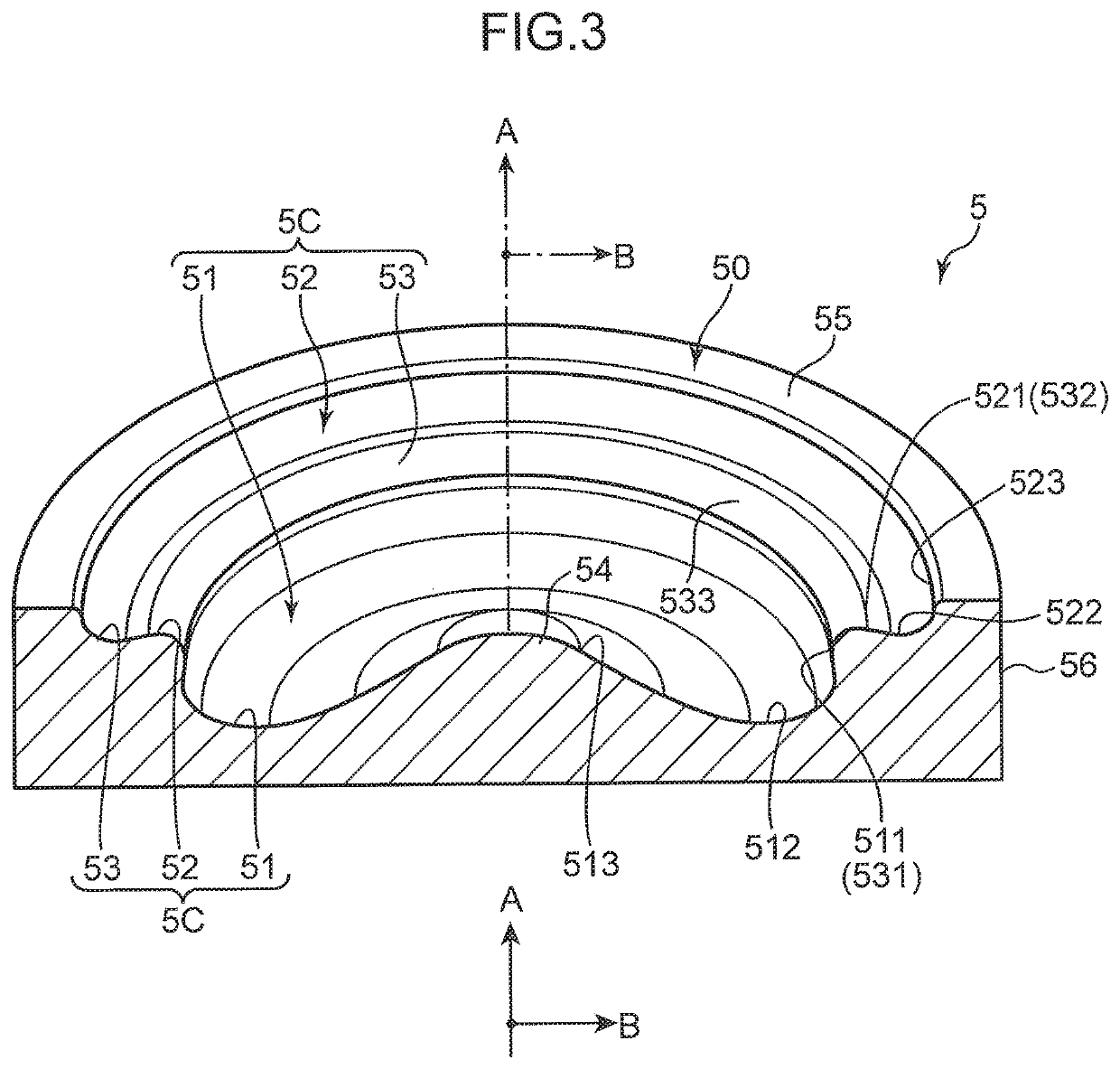
An engine combustion chamber structure includes a combustion chamber of an engine and a fuel injection valve. The fuel injection valve injects fuel toward a cavity in a crown face of a piston. The cavity includes a first cavity that is provided in a radially central region of the crown face with a first bottom having a first depth, a second cavity provided in an outer side of the first cavity with a second bottom having a second depth being smaller than the first depth, a connecting portion, and a standing wall region disposed further in a radially outer side than the second bottom of the second cavity. The second bottom is provided lower than an upper end, of the connecting portion. A lower section of the standing wall region is provided further in a radially inner side than an upper edge of the standing wall region.
Description
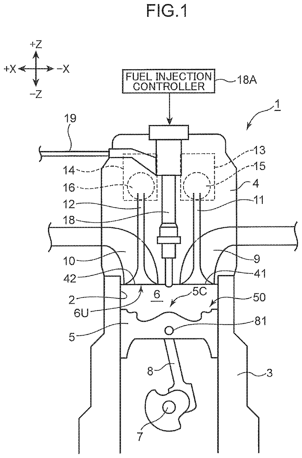
TECHNICAL FIELD[0001]The present invention relates to an engine combustion chamber structure including a cylinder and a piston.BACKGROUND ART[0002]A combustion chamber of an engine for a vehicle, such as a car, is formed by an inner wall face of a cylinder, a bottom face of a cylinder head (top face of the combustion chamber), and a crown face of a piston. Fuel is supplied into the combustion chamber from a fuel injection valve. In a known combustion chamber structure, a cavity (recess) is provided in the crown face of the piston, and fuel is injected from the fuel injection valve toward the cavity. Patent Literature 1 discloses a combustion chamber structure including the cavity having a two-stage structure including an upper cavity and a lower cavity.[0003]To reduce emission from the engine, such as NOx, CO, HC, and PM (soot), it is important not to create a locally high temperature region and a region short of oxygen while a mixed gas is combusted in the combustion chamber. In th...
Claims
Login to View More Application Information
Patent Timeline
 IPC IPC(8): F02D41/40F02F1/24F02F3/12
CPCF02F3/12F02F1/24F02D41/401F02D41/403F02B23/0672F02D41/3827F02F3/26F02B23/0693F02B23/0651F02D13/0219Y02T10/12Y02T10/40
InventorKIM, SANGKYUSUMIMOTO, TAKASHISHIMO, DAISUKEHARADA, TOMONORIOKADA, SHINTAROTAKUMA, SHUJI
OwnerMAZDA MOTOR CORP