Integration of forced egr/egr-pump into egr-cooler

Active Publication Date: 2015-10-01
HANON SYST
View PDF8 Cites 7 Cited by
  • Summary
  • Abstract
  • Description
  • Claims
  • Application Information

AI Technical Summary

Benefits of technology

The invention is about a device with a one-piece housing made of aluminum, which can be casted using expensive constructions. This reduces manufacturing costs and weight, which results in savings in fuel and carbon dioxide emissions. The use of aluminum also allows for the production of complex housing constructions for the compressor. The device enables the recycling of exhaust gas to make the engine more efficient with less emissions. This can reduce fuel consumption by up to 5%.

Problems solved by technology

However, the mixing in of the recycled current of exhaust gas with high temperatures reduces the cooling effect and also the degree of efficiency of the internal combustion engine.
Laws regarding the standards for exhaust gases and requirements for fuel consumption in motor vehicles are becoming increasingly strict, bringing about an increased cooling requirement.
Additionally, space for the components in the motor vehicle is becoming smaller and smaller.
In certain arrangements for removing a part of the exhaust gas or for feeding the exhaust gas into the fresh air on the intake side, or in certain operating modes of the internal combustion engine, the pressure gradient is not sufficient for transferring the mass flow of the exhaust gas, which is the case, in particular, in the design of the system for the recycling of exhaust gas at low pressure.
The separate construction has as a consequence an elevated number of structural components, an elevated space requirement, a high weight, and elevated manufacturing and assembly costs as a consequence.
In addition, possible positive thermodynamic and engineering interactions between the exhaust gas heat exchanger and the compressor cannot be utilized.

Method used


Image

  • Integration of forced egr/egr-pump into egr-cooler
  • Integration of forced egr/egr-pump into egr-cooler
  • Integration of forced egr/egr-pump into egr-cooler

Examples


Embodiment Construction

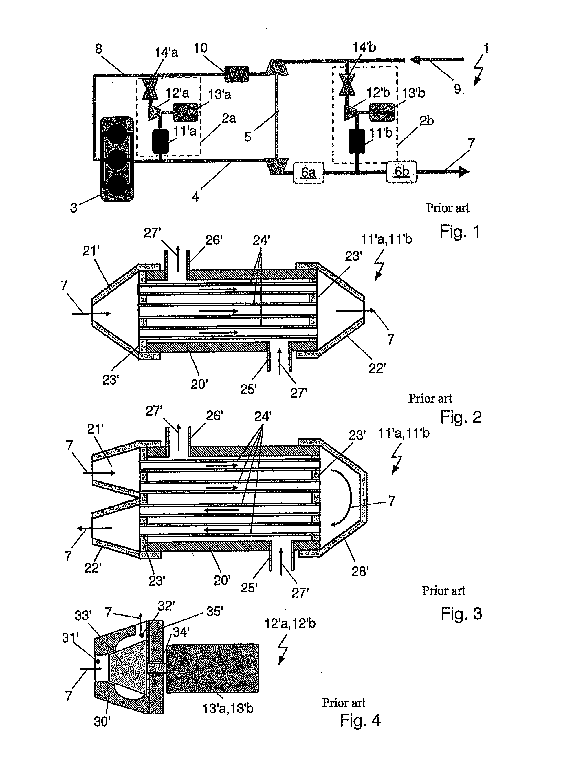
[0056]FIG. 1 shows a system 1 for guiding air of an internal combustion engine 3 with arrangements 2a, 2b for recycling exhaust gas from the prior art.

[0057]The system 1 comprises a suction intake line 8 for drawing in combustion air for the internal combustion engine 3. Fresh air is drawn in from an environment through the suction intake line 8 via the compressor side of a turbocharger 5 in direction of flow 9. The compressed air is conducted via a loading air cooler 10 to the internal combustion engine 3 and distributed into individual cylinders. The exhaust gas generated during combustion is removed through the exhaust gas line 4 via the turbine side of the turbocharger 5. The turbine side and the compressor side of the turbocharger 5 are mechanically coupled, for example, by a shaft, so that the turbine drives the compressor and therefore the throughput of air is increased and the suction intake work of the pistons of the internal combustion engine 3 are reduced. Consequently, t...


PUM


Abstract

A device for the recycling of exhaust gas of an internal combustion engine in a motor vehicle. The device comprises an exhaust gas heat exchanger constructed with a first housing element with an inlet and an outlet for the exhaust gas and at least one inlet and at least one outlet for a coolant, and a compressor which is constructed with a second housing element with an inlet and an outlet for the exhaust gas. The first housing element of the exhaust gas heat exchanger and the second housing element of the compressor are constructed as a housing connected to a cohesive, compact component so that the exhaust gas heat exchanger and the compressor are arranged inside the housing.

Description

CROSS-REFERENCE TO RELATED APPLICATION[0001]This application claims priority to German Provisional Patent Application Serial No. DE 10 2014 104 093.7 filed on Mar. 25, 2014 and German Non-Provisional Patent application Serial No. DE 10 2015 104 179.0 filed Mar. 20, 2015, hereby incorporated herein by reference in their entirety.FIELD OF THE INVENTION[0002]The invention relates to a device for the recycling of exhaust gas of an internal combustion engine in a motor vehicle. The device is provided with an exhaust gas heat exchanger and a compressor, wherein the exhaust gas heat exchanger comprises a first housing element and the compressor comprises a second housing element.BACKGROUND[0003]Systems for the recycling of exhaust gas in motor vehicles are known from the prior art. These systems reduce the nitrogen oxides in the exhaust gases, in particular in the exhaust gases of motor vehicles operated with diesel fuel, and reduce fuel consumption of motor vehicles operated with gasoline...

Claims


Application Information

Patent Timeline
IPC IPC(8): F02M25/07F01N3/02
CPCF01N3/0205F02M25/0726F02M26/29F02M26/05F02M26/06F02M26/24F02M26/32Y02T10/12F02M26/30F02M26/34F28F9/0219F28F2250/06
Inventor OHREM, CARSTENDIEHL, PETER
Owner HANON SYST
Why Eureka
Try Eureka