Extended target-matched cfar detector

a cfar detector and target-matched technology, applied in the field of extended target-matched cfar detectors, can solve the problems of less than optimal detection performance of such cfar detectors, and achieve the effect of increasing the overall detection performan

Active Publication Date: 2020-12-24
GM GLOBAL TECH OPERATIONS LLC
View PDF0 Cites 3 Cited by
  • Summary
  • Abstract
  • Description
  • Claims
  • Application Information

AI Technical Summary

Benefits of technology

[0001]Radar systems are often employed to assist in the detection and localization of potential obstacles in proximity to a host device. When a radar system is used aboard a motor vehicle, for example, the radar system may be used to detect other vehicles, pedestrians, and stationary objects in real-time. Radar is therefore an enabling technology for various driver assist subsystems, regardless of whether the driver is a human operator, or the motor vehicle is autonomously-controlled. Such subsystems may include adaptive cruise control, automatic lane-changing / lane-keeping, automatic braking or steering, backup assistance, etc. Radar-based obstacle detection is also used to enhance the overall situational awareness of a vehicle operator by triggering timely alerts.
[0002]In a typical radar system, pulsed or continuous-wave radio frequency (RF) or other electromagnetic spectrum energy is transmitted as a calibrated set of radio waves in a predetermined scanning direction, such as a forward, lateral, and / or rear direction relative to a vehicle body. If the transmitted RF waveform encounters a sufficiently reflective object as the waveform propagates through free space, some of the initially-transmitted energy is reflected back toward the host, whereupon the reflected energy is received by an antenna. The corresponding return signature is then processed using signal processing hardware and software. In this manner, a radar system is able to quickly determine the direction (i.e., azimuth and elevation) and a corresponding range to a detected target.SUMMARY
[0005]As will be appreciated by those of ordinary skill in the art, vehicles and other host systems may use a technique referred to as Constant False-Alarm Rate (CFAR) detection to positively identify radar targets from associated background noise via energy or power-based spectral analysis. In a typical CFAR detector, a single point cell under consideration is used across a range of potential radar targets, with an energy threshold. For example, in a vehicle radar system the CFAR detector is required to detect cars, trucks, motorcycles, pedestrians, trees, and roadside barriers together with the same single point cell detector. However, the detection performance of such CFAR detectors may be less than optimal, either leading to a low false alarm rate with a high number of undetected targets or a high false alarm rate with a low number of undetected targets. The present approach is tailored to improving upon such state of the art CFAR detectors and thereby increasing overall detection performance.

Problems solved by technology

However, the detection performance of such CFAR detectors may be less than optimal, either leading to a low false alarm rate with a high number of undetected targets or a high false alarm rate with a low number of undetected targets.

Method used


Image

  • Extended target-matched cfar detector
  • Extended target-matched cfar detector
  • Extended target-matched cfar detector

Examples


Embodiment Construction

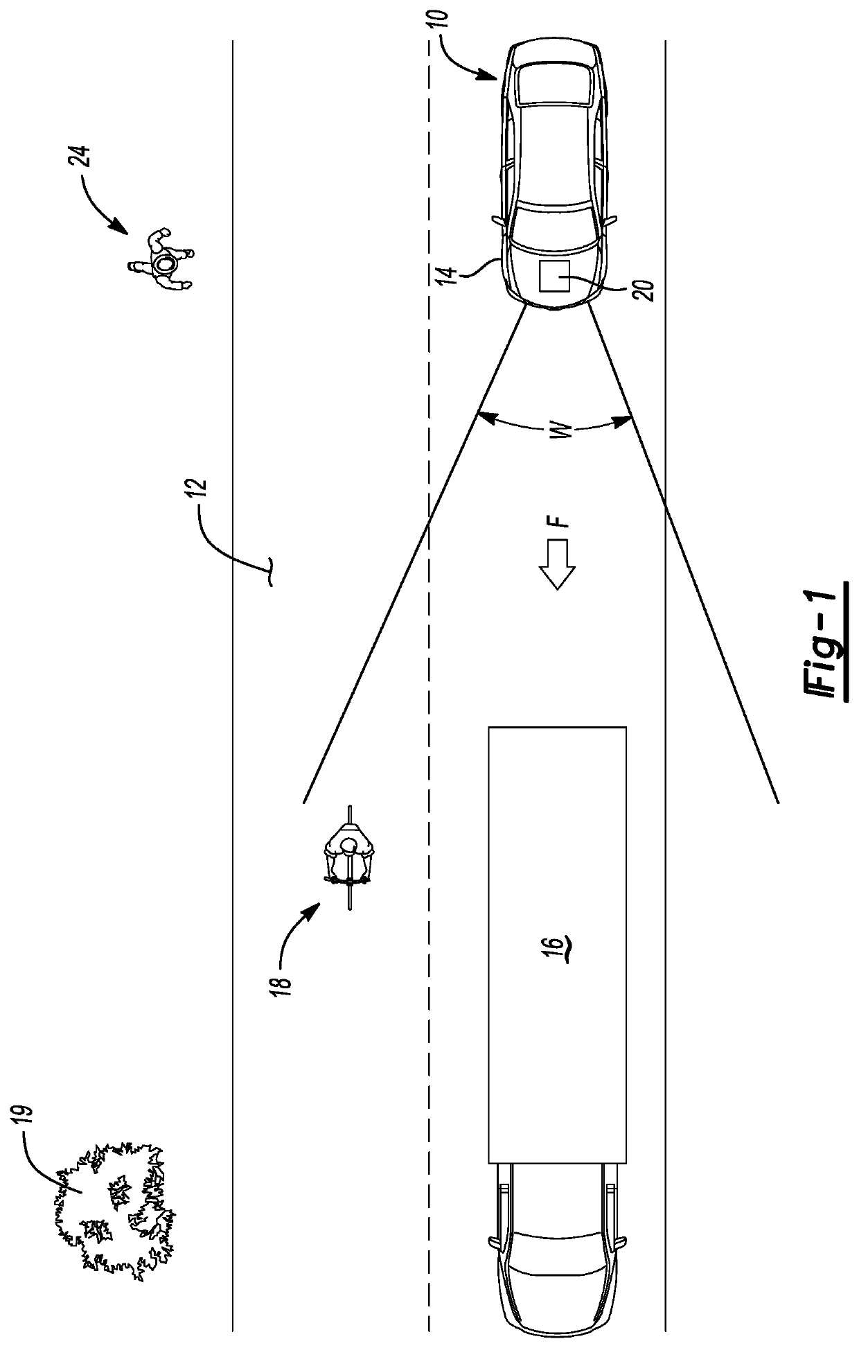
[0022]Referring to the drawings, wherein like reference numbers refer to like components, a host vehicle 10 is depicted schematically in FIG. 1. The host vehicle 10 in the illustrated embodiment is a motor vehicle. However, those of ordinary skill in the art will appreciate that other vehicles may benefit from the present teachings, including but not limited to watercraft, aircraft, and rail vehicles, or other mobile systems such as robots or mobile platforms. Stationary host systems may also benefit from the present teachings. For illustrative consistency, the host vehicle 10 will be described hereinafter as a motor vehicle without limiting the scope of the disclosure to such an embodiment.

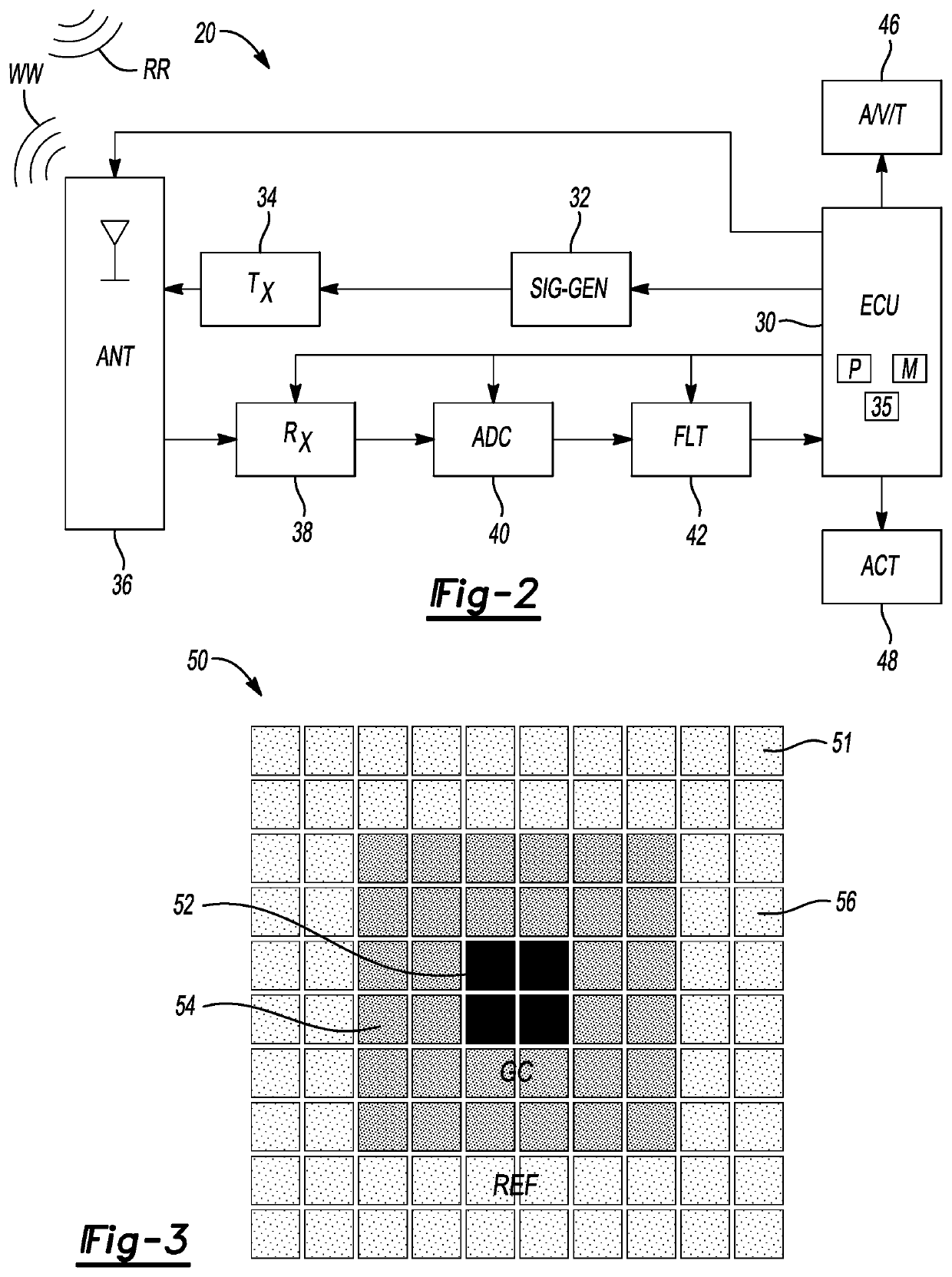
[0023]The host vehicle 10 includes a vehicle body 14 and a radar circuit 20, an example embodiment of the latter being described in detail below with reference to FIG. 2. The host vehicle 10, when optionally configured as a motor vehicle as shown, may travel in the general direction of arrow F al...


PUM


Abstract

A radar circuit for use with a host system such as a vehicle includes a radio frequency (RF) signal generator configured to generate a predetermined RF waveform, an RF antenna connected to the RF signal generator, and an ECU which executes a method. As part of such a method, a signal generator transmits the RF waveform toward different radar target types, and receives return signatures reflected therefrom. The ECU receives the return signatures from the antenna, processes the return signatures via parallel constant false-alarm rate (CFAR) subdetectors each with defined cells under test to detect the target types as a set of detection events, merges the detection events into a merged set, and executes a control action aboard the host system responsive to the merged set. Each subdetector detects a corresponding one or more of the radar target types via corresponding detection parameters.

Description

INTRODUCTION[0001]Radar systems are often employed to assist in the detection and localization of potential obstacles in proximity to a host device. When a radar system is used aboard a motor vehicle, for example, the radar system may be used to detect other vehicles, pedestrians, and stationary objects in real-time. Radar is therefore an enabling technology for various driver assist subsystems, regardless of whether the driver is a human operator, or the motor vehicle is autonomously-controlled. Such subsystems may include adaptive cruise control, automatic lane-changing / lane-keeping, automatic braking or steering, backup assistance, etc. Radar-based obstacle detection is also used to enhance the overall situational awareness of a vehicle operator by triggering timely alerts.[0002]In a typical radar system, pulsed or continuous-wave radio frequency (RF) or other electromagnetic spectrum energy is transmitted as a calibrated set of radio waves in a predetermined scanning direction, ...

Claims


Application Information

Patent Timeline
Patent Type & Authority Applications(United States)
IPC IPC(8): G01S13/56G01S13/93B60W50/14
CPCB60W2420/52B60W50/14G01S13/56G01S13/931G05D1/0257G01S13/582G01S13/584G01S7/2927
Inventor LONGMAN, ORENSOLODKY, GASTONVILLEVAL, SHAHARBILIK, IGAL
Owner GM GLOBAL TECH OPERATIONS LLC
Why Eureka
Try Eureka