

Manufacturing method for slab and continuous casting equipment
a manufacturing method and continuous casting technology, applied in the direction of manufacturing tools, metal rolling arrangements, profile control devices, etc., can solve the problems of difficult to judge whether or not the oxide scale has been caught, the surface quality of the slab deteriorates, and the slab is visible after rolling. achieve the effect of not impairing productivity
- Summary
- Abstract
- Description
- Claims
- Application Information
AI Technical Summary
Benefits of technology
Problems solved by technology
Method used
Image

Examples
examples
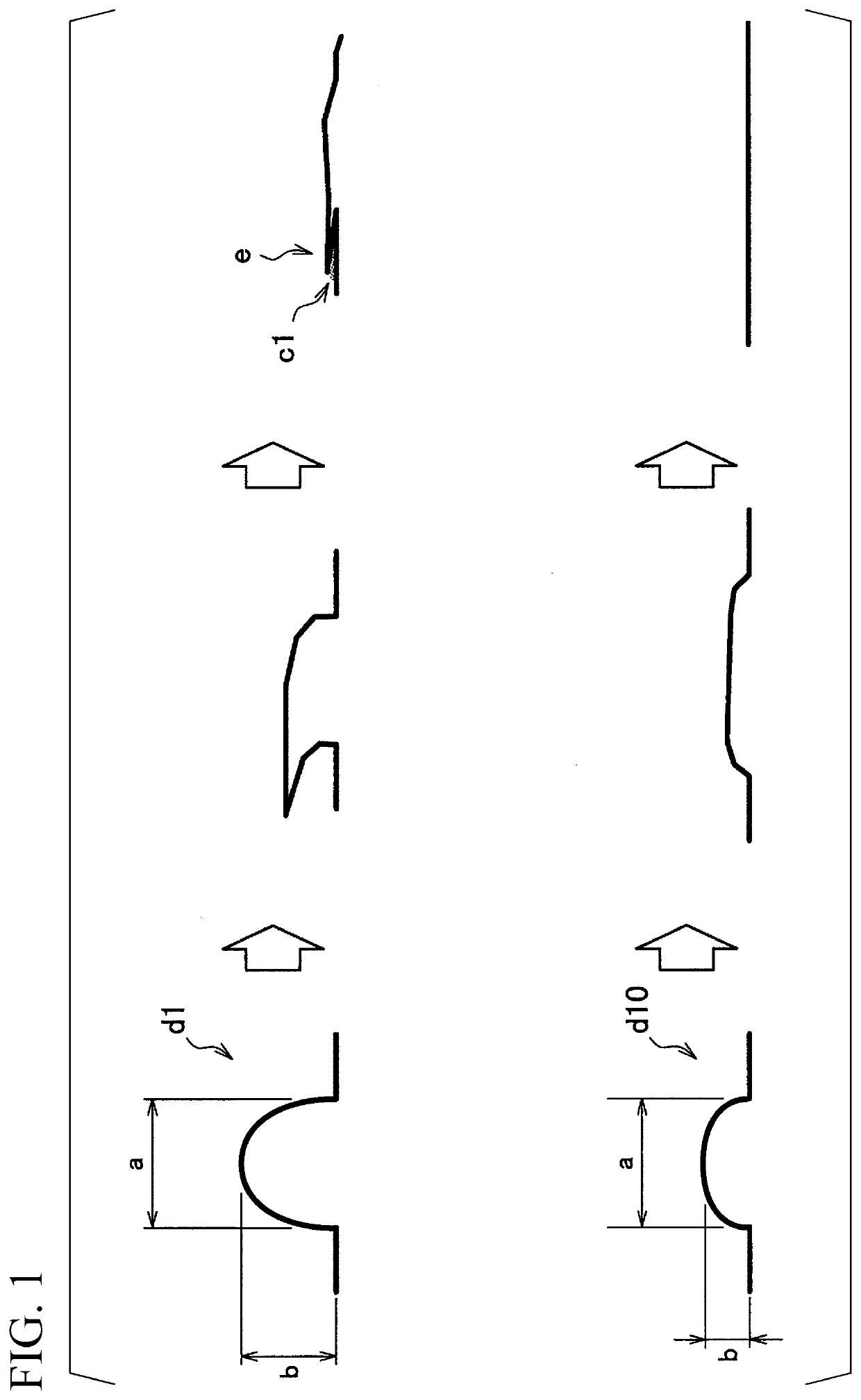
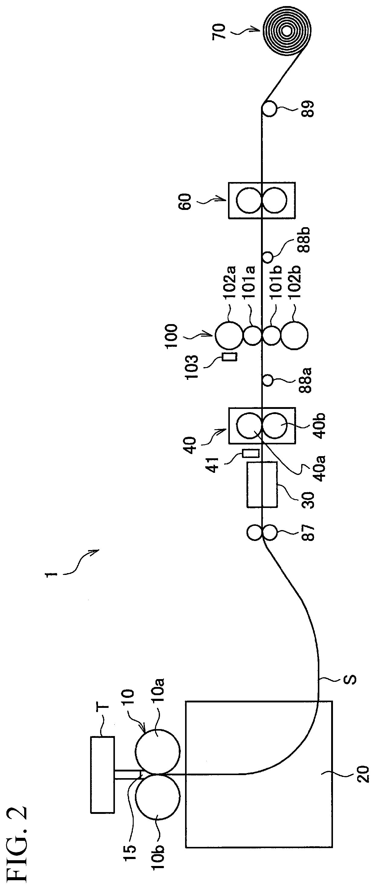
[0095]In order to confirm the effect of the present invention, by use of an equipment similar to the continuous casting equipment 1 according to the present embodiment illustrated in FIG. 2, the presence or absence or the like of occurrence of folding of a protrusion of a slab formed by dimples was investigated. In each of an example and a comparative example, a slab having protrusions each having a width of 2 mm in the rolling direction and a height of 130 μm was used.
[0096]The present example was performed in manufacturing steps of a slab having a configuration similar to that in FIG. 2. In the present example, ordinary steel having a plate thickness of 2 mm and a plate width of 1200 mm was used. An acceleration rate of the cooling drum from the start of casting was 150 m / min / 30 seconds, and a rotation speed of the cooling drum in the steady state was 150 m / min. Note that an initial profile of the cooling drum was processed so that a plate crown of the slab was 43 μm in the steady...
PUM
| Property | Measurement | Unit |
|---|---|---|
| height | aaaaa | aaaaa |
| height | aaaaa | aaaaa |
| width | aaaaa | aaaaa |
Abstract
Description
Claims
Application Information