Roller shade actuation device

a technology of roller shade and actuation device, which is applied in the field of window shade, can solve the problems of large volume of the overall roller shade actuation device and complex assembly structure, and achieve the effect of reducing the volum

Active Publication Date: 2020-12-31
LEAFY WINDOWARE CO LTD
View PDF0 Cites 1 Cited by
  • Summary
  • Abstract
  • Description
  • Claims
  • Application Information

AI Technical Summary

Benefits of technology

[0003]Therefore, the technical problem to be solved by the embodiments of the present invention is to provide a roller shade actuation device, which effectively reduces the occupied volume.
[0013]By adopting the above-mentioned technical solutions, the beneficial effects of the embodiments of the present invention are as follows. The axial direction of the output shaft of the rotation power member and the axial direction of the shaft are vertically arranged. The first transmission gear which meshes with the driving gear fixed to the output shaft, the synchronous gear coaxial with and relatively fixed to the first transmission gear, and the fixed gear fixed to the shaft and meshing with the synchronous gear are provided. The shaft is relatively fixed to the support frame. When the rotation power member outputs rotary power, since the fixed gear is relatively fixed, the synchronous gear rotates about its own axis and also rotates about the axial direction of the fixed gear, and the housing of the driver and the winding drum are relatively fixed, the winding drum can rotate with the synchronous gear about the axial direction of the fixed gear to realize the winding of the shade body. The structure is simple, and moreover, the output shaft of the rotation power member and the axial direction of the shaft are arranged vertically, and thus, the space layout is reasonably used, and the occupied volume is reduced. The synchronous gear and the fixed gear are bevel gears whose axial directions are perpendicular to each other, which can effectively realize the power transmission in the vertical direction.

Problems solved by technology

An output shaft of a driver of the current spring roller shade and the winding drum are arranged in parallel in the axial direction, and flat scroll springs are all set parallel to the output shaft, which makes the overall roller shade actuation device take up a great volume, and the assembly structure is also complicated.

Method used


Image

  • Roller shade actuation device
  • Roller shade actuation device
  • Roller shade actuation device

Examples


Embodiment Construction

[0017]The present application will be further described in detail below with reference to the accompanying drawings and specific embodiments. It should be understood that the following illustrative embodiments and illustrations are only used to explain the present invention and are not intended to limit the invention, and that the embodiments of the present invention and the features of the embodiments can be combined with each other without conflict.

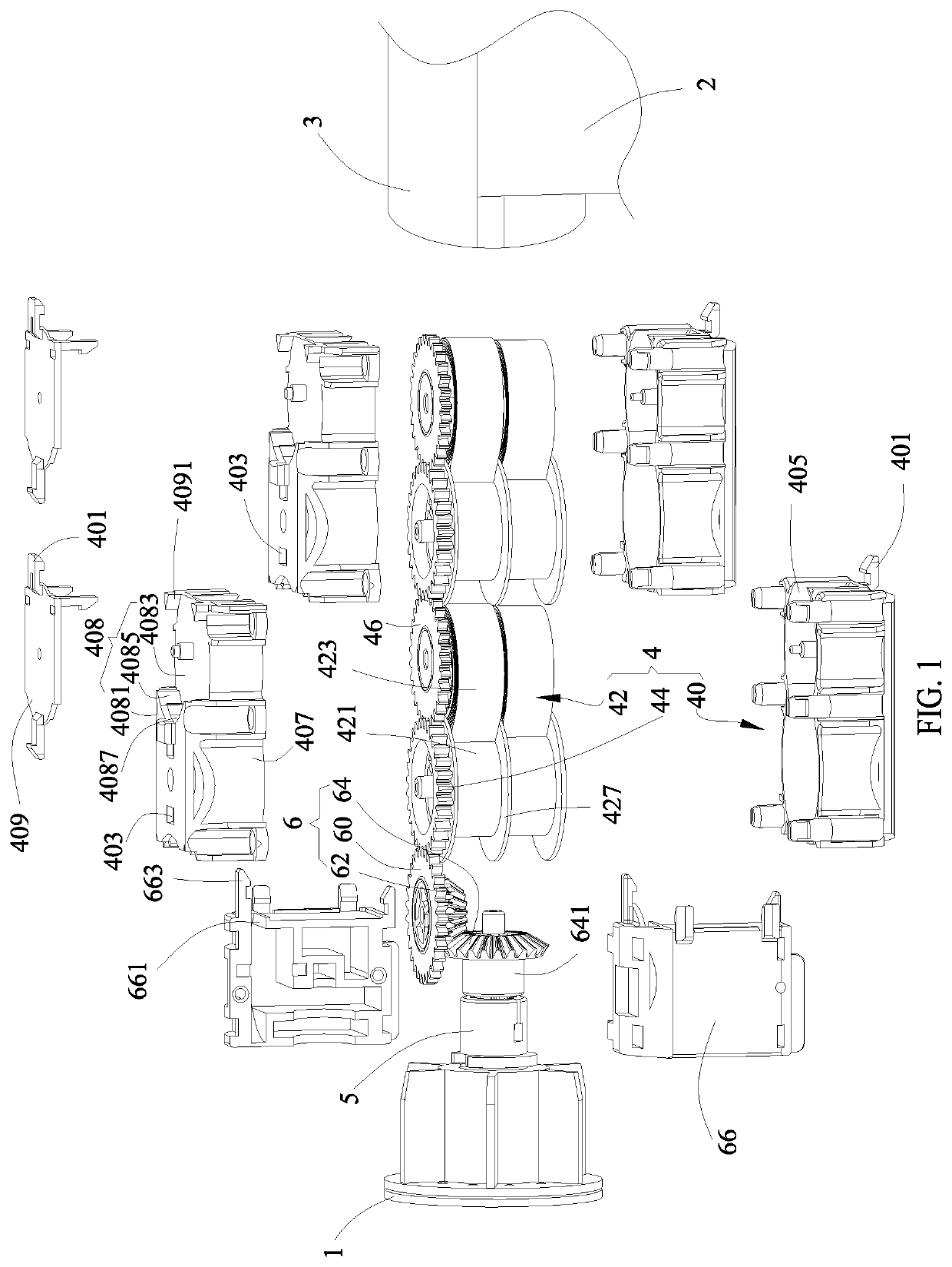
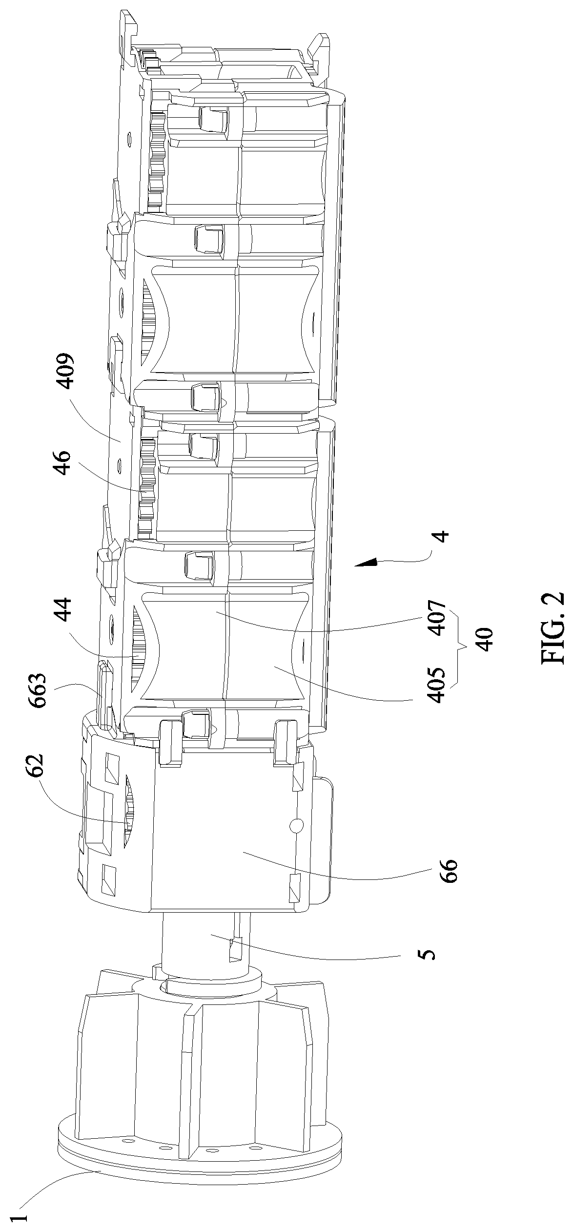
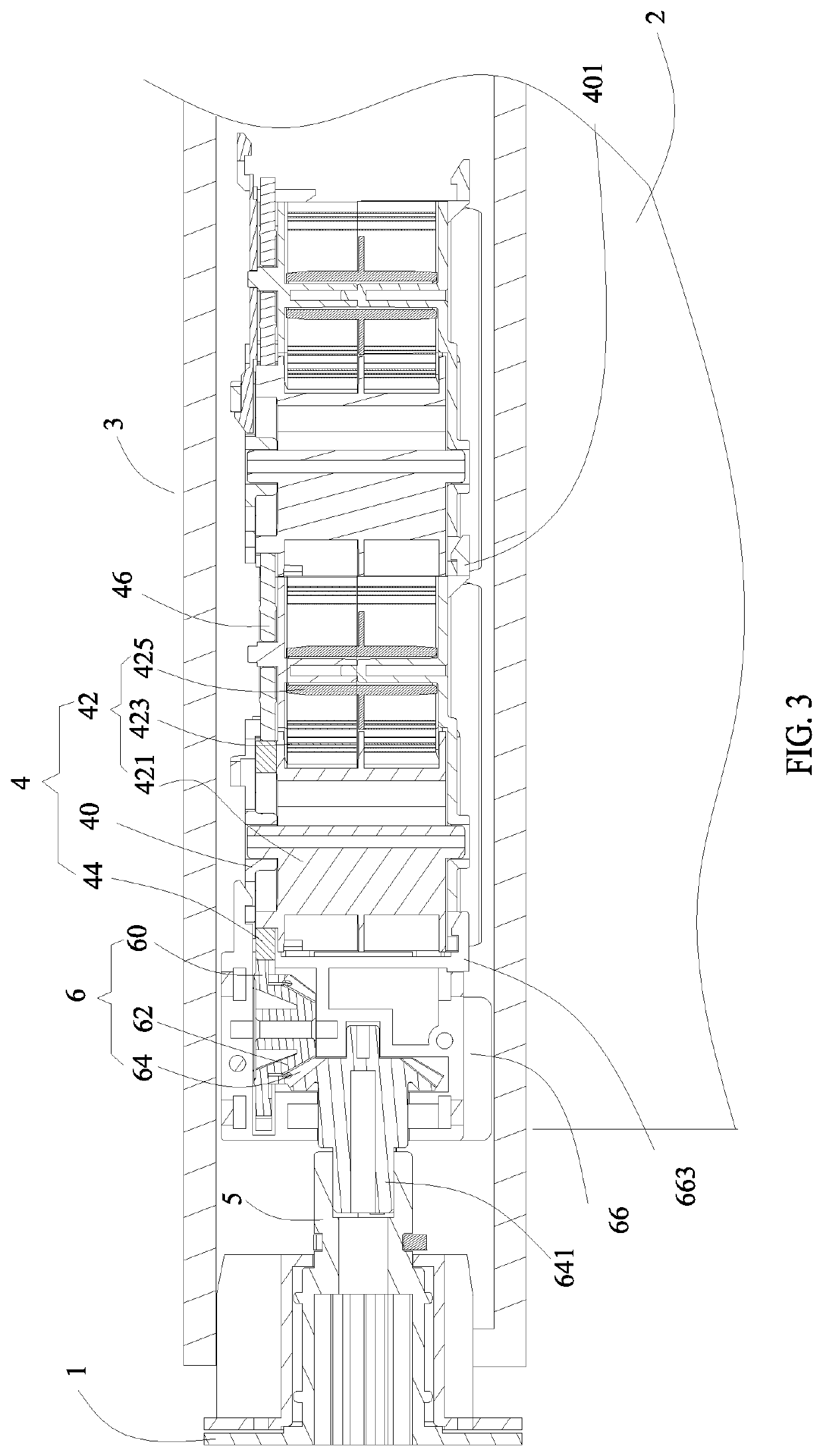
[0018]Referring to FIGS. 1-3, an embodiment of the present disclosure provides a roller shade actuation device for actuating a winding drum 3. Opposite ends of the winding drum 3 are mounted to corresponding support frames 1, and an outer surface of the winding drum 3 is mounted with an end of a shade body 2. The roller shade actuation device includes a driver 4 arranged in the winding drum 3, a shaft 5 fixed to the support frame 1 outside one end of the winding drum 3 and inserted into the winding drum 3, and a transmission mechanism 6...


PUM


Abstract

A roller shade actuation device includes a driver arranged in a winding drum, a shaft fixed to a support frame outside one end of the winding drum and inserted into the winding drum, and a transmission mechanism for realizing power transmission between the driver and the shaft. The driver includes a housing relatively fixed to the winding drum, a rotation power member arranged in the housing, and a driving gear coaxial with and fixed to an output shaft of the rotation power member. The transmission mechanism includes a first transmission gear meshed with the driving gear, a synchronous gear coaxial with the first transmission gear, and a fixed gear fixed to the shaft and meshed with the synchronous gear. Axial directions of the output shaft and the shaft are vertical, and the synchronous gear and the fixed gear are bevel gears whose axial directions are perpendicular to each other.

Description

BACKGROUND OF THE INVENTION1. Field of the Invention[0001]The present invention relates to window shade technical field and, more particularly to a roller shade actuation device.2. Description of Related Art[0002]Opposite ends of a winding drum of a current spring roller shade are mounted to corresponding frames, and a spring end, a coil spring, a damper, and a limiter are arranged in order from an end to an opposite end in the winding drum. When the shade body needs to be put down, the shade body only needs to be pulled down, and the shade body will drive the winding drum to rotate and then rotate relative to the coil spring. The coil spring is twisted and deformed to accumulate elastic force. At the same time, by means of the damper, the shade body can be held at any height position within the effective range of the shade body. When the shade body needs to be rolled up, the shade body only needs to be pushed up, and the force of the coil spring overcomes the damping action of the ...

Claims


Application Information

Patent Timeline
Patent Type & Authority Applications(United States)
IPC IPC(8): E06B9/68E06B9/42
CPCE06B9/68E06B9/42E06B9/60
Inventor LEI, ZHENBANGLEI, XINGBANG
Owner LEAFY WINDOWARE CO LTD
Why Eureka
Try Eureka