Touch sensor, and window laminate and image display device including the same

Active Publication Date: 2020-12-31
DONGWOO FINE CHEM CO LTD
View PDF0 Cites 0 Cited by
  • Summary
  • Abstract
  • Description
  • Claims
  • Application Information

AI Technical Summary

Benefits of technology

[0033]According to the touch sensor of the present invention having such a configuration, the bending portion of the touch sensor can be easily bent by minimizing or optimizing the thicknesses of a bending portion touch sensor layer and a bending portion protective layer protecting the bending portion touch sensor layer.
[0034]According to the touch sensor of the present invention, it is possible to prevent or minimize damage to the bending portion touch sensor layer by optimizing the elastic modulus of the bending porti

Problems solved by technology

However, such base layer 110 is thick and has a high elastic modulus to satisfy a supporting role, which may make t

Method used


Image

  • Touch sensor, and window laminate and image display device including the same
  • Touch sensor, and window laminate and image display device including the same
  • Touch sensor, and window laminate and image display device including the same

Examples


Example

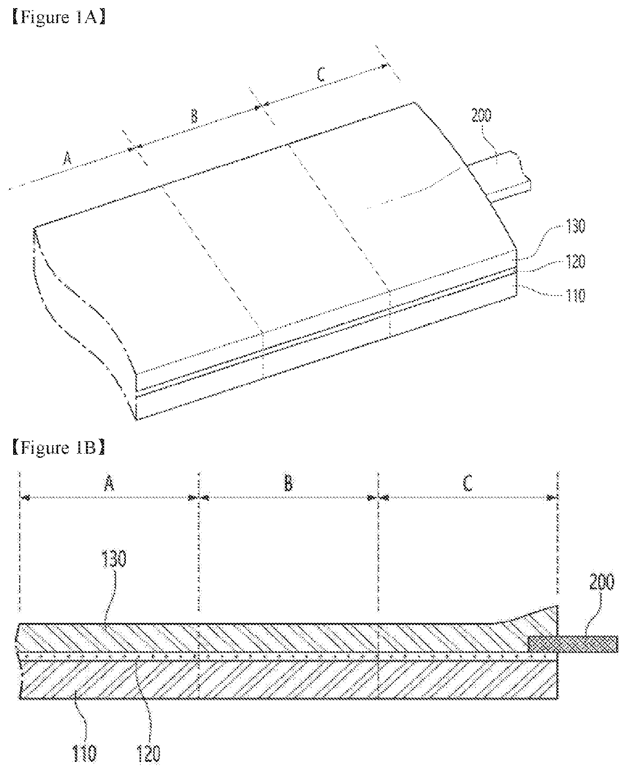
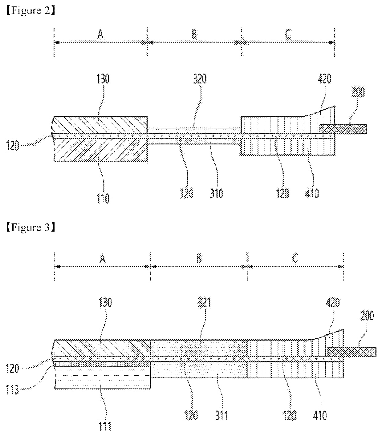
[0045]FIG. 2 is a sectional view of the first embodiment of a touch sensor having a bending portion according to the present invention.

[0046]As shown in FIG. 2, the first embodiment of the touch sensor according to the present invention may be configured by a display portion A, a bending portion B, a bonding portion C, and so on.

[0047]The display portion A may be configured by a base layer 110, a display portion touch sensor layer 120, a display portion protective layer 130, and so on.

[0048]As the base layer 110, a film with good transparency, mechanical strength and thermal stability may be used. Specific examples may include a film made of thermoplastic resins, e.g., polyester resins such as polyethylene terephthalate, polyethylene isophthalate, polyethylene naphthalate and polybutylene terephthalate; cellulose resins such as diacetylcellulose and triacetylcellulose; polycarbonate resins; acrylate resins such as polymethyl (meth)acrylate and polyethyl (meth)acrylate; styrene resin...

Example

[0082]FIG. 3 is a sectional view illustrating the second embodiment of a touch sensor having a bending portion according to the present invention.

[0083]As shown in FIG. 3, in the second embodiment, a display portion A may be configured of a polarizing film 111, a PSA 113, a display portion touch sensor layer 120, a display portion protective layer 130, and so on. The PSA 113 may couple the polarizing film 111 serving as a base layer to the display portion touch sensor layer 120.

[0084]A bending portion B may be configured of a bending portion touch sensor layer 120, a lower UV curable resin 311 coupled to the lower surface of the bending portion touch sensor layer 120, and an upper UV curable resin 321 coupled to the upper surface of the bending portion touch sensor layer 120. The bending portion touch sensor layer 120 may have a thickness of 2 to 10 μm. The lower and upper UV curable resins 311 and 321 may have elastic moduli of 0.1 to 1000 Mpa and thicknesses of 1 to 200 μm, respec...

Example

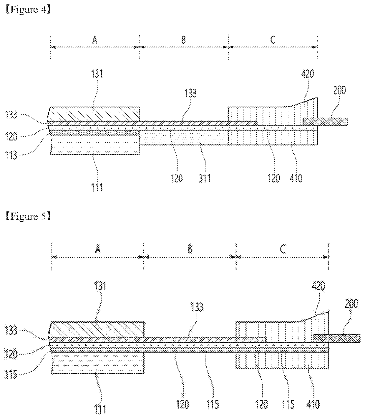
[0086]FIG. 4 is a sectional view illustrating the third embodiment of a touch sensor having a bending portion according to the present invention.

[0087]As shown in FIG. 4, in the third embodiment, a display portion A may be configured of a polarizing film 111, a PSA 113, a display portion touch sensor layer 120, an upper OCA 133, a release film 131, and so on. The PSA 113 may couple the polarizing film 111 serving as a base layer to the display portion touch sensor layer 120. The upper OCA 133 may protect the upper surface of the display portion touch sensor layer 120 and couple the release film 131 to the display portion touch sensor layer 120.

[0088]A bending portion B may be configured of a bending portion touch sensor layer 120, a lower UV curable resin 311 coupled to the lower surface of the bending portion touch sensor layer 120, and an upper OCA 133 coupled to the upper surface of the bending portion touch sensor layer 120. The upper OCA 133 of the bending portion B may be the ...


PUM


Abstract

A touch sensor includes: a display portion including a base layer and a touch sensor layer on the base layer; a bending portion extending from the display portion and including a first part of a trace electrically connected to the touch sensor layer but not including the base layer; and a bonding portion extending from the bending portion and including a second part of the trace, wherein an end portion of the second part of the trace is connected to a flexible circuit board.

Description

CROSS REFERENCE TO RELATED APPLICATIONS[0001]The instant application claims priority based on Korean Patent Application No. 10-2019-0075483 fled Jun. 25, 2019 and Korean Patent Application No. 10-2019-0080948 filed Jul. 4, 2019, the entire contents of which are hereby incorporated by reference.TECHNICAL FIELD[0002]The present invention relates to a touch sensor. Particularly, the present invention relates to a touch sensor having a bending portion.BACKGROUND ART[0003]A display device is a device that displays information externally, examples of which include a liquid crystal display device, a plasma display panel device, an electroluminescent display device, and an organic light-emitting diode display device.[0004]The display device includes a touch sensor panel that is an apparatus for inputting a user's command by touching contents displayed on the screen with a finger or a pen. The touch sensor panel includes a plurality of sensing electrodes that sense a contact position. The se...

Claims


Application Information

Patent Timeline
IPC IPC(8): G06F3/041H05K1/02
CPCG06F3/0412H05K1/0281G06F2203/04102G06F3/0416G06F3/041H05K3/361H05K2201/10128
Inventor KIM, JUNHALEE, JIN KOOLEE, WONJONG
Owner DONGWOO FINE CHEM CO LTD
Why Eureka
Try Eureka