Enhanced physiological monitoring devices and computer-implemented systems and methods of remote physiological monitoring of subjects
What is Al technical title?
Al technical title is built by PatSnap Al team. It summarizes the technical point description of the patent document.
a physiological monitoring and enhanced technology, applied in the field of monitoring and analyzing data, can solve the problems of inconvenient disposable, high cost of conventional monitoring equipment, labor and time-consuming,
Pending Publication Date: 2021-01-07
SEMPULSE CORP
View PDF0 Cites 23 Cited by
Summary
Abstract
Description
Claims
Application Information
AI Technical Summary
This helps you quickly interpret patents by identifying the three key elements:
Problems solved by technology
Method used
Benefits of technology
[0009]In some embodiments of the present disclosure, a monitoring device is provided. The monitoring device includes a plurality of physiological sign monitoring portions. Each physiological sign monitoring portion of the monitoring device is configured for deployment on a different, respective surface of a subject. The different, respective surfaces of the subject are a surface on the back of a respective ear (e.g., opposite a concha) of the subject, a surface over a mastoid region of the neck of the subject, a surface over another region of the neck of the subject, and a skull, nose, or face surface of the subject opposite a portion of an eyeglasses physiological sign monitoring portion. Each physiological sign monitoring portion of the monitoring device includes a plurality of physiological sensors. Each physiological sensor is configured to generate a respective electronic signal based on a respective monitored physiological parameter of the subject. The monitored physiological parameters include at least two of photoplethysmogram, electrocardiogram, ballistocardiogram, electrooculogram, skin temperature, skin conductance, skin resistance, head motion relative to a motion axis, neck motion relative to a motion axis, sweat chemistry, sweat composition, head orientation relative to an orientation axis, and neck orientation relative to an orientation axis. At least one physiological sensor in each physiological sign monitoring portion of the monitoring device is configured to generate a respective electronic signal based on the same monitored physiological parameter of the subject.
Problems solved by technology
However, these conventional monitoring techniques are very costly, and both labor and time-intensive, and such conventional monitoring equipment is very expensive and not readily disposable.
These conventional techniques and equipment are also ineffective at monitoring ambulatory patients.
Further, such dedicated equipment is highly sensitive, and designed and tested for sterile ambulatory and hospital conditions, which leaves government, commercial, and military health providers and first responders without an effective solution for monitoring ambulatory patients, especially in trauma, battlefield, natural disaster, or terrorist attack, scenarios where mud, blood, and other contaminates are prevalent.
Current administrative policies, and an aging demographic, have resulted in a 25% annual increase in emergency room wait times. The problem continues to grow as over 800,000 people visit emergency rooms and urgent care centers in the U.S. daily, and longer wait times equate to more deaths, posing a significant risk and liability of a humanitarian disaster.
However, deploying such wearables on extremity locations such as the wrist introduces significant errors associated with vital or physiological sign measurement.
Moreover, the body naturally restricts blood flow to extremities during emergency situations (e.g., cold temperatures and emotional stress).
Method used
Image
Click on the blue label to locate the original text in one second.
Reading with bidirectional positioning of images and text.
Examples
Embodiment Construction
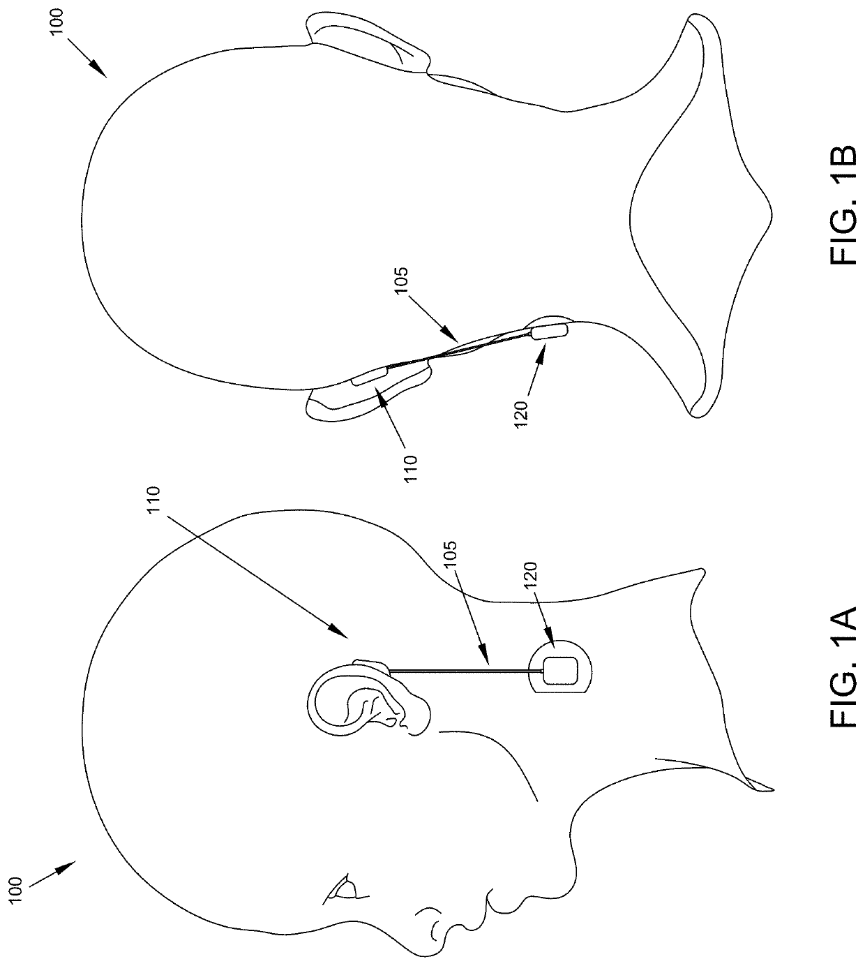
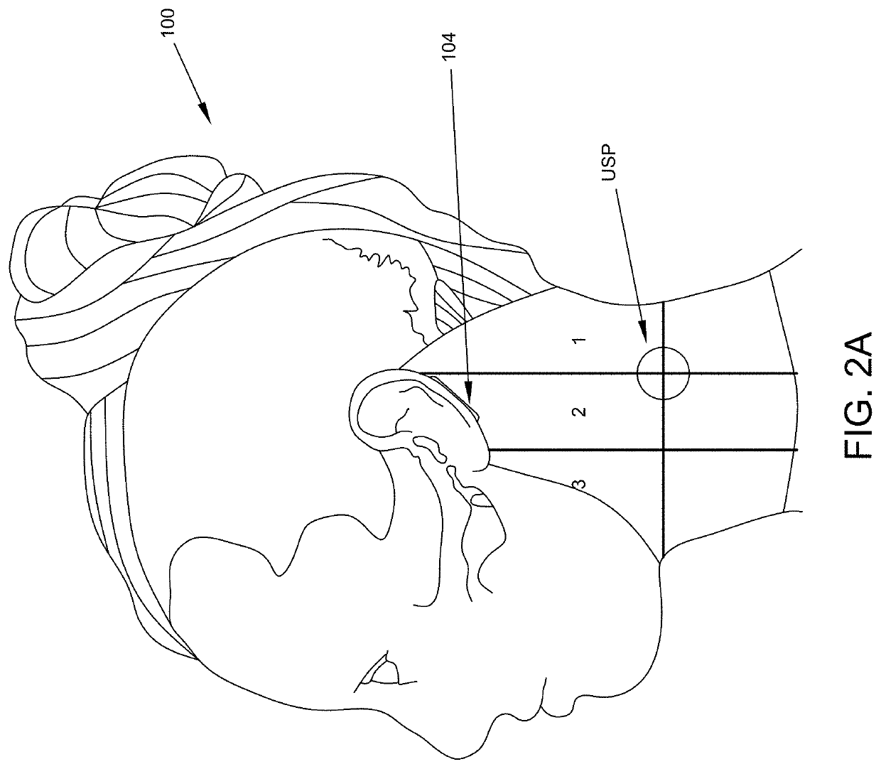
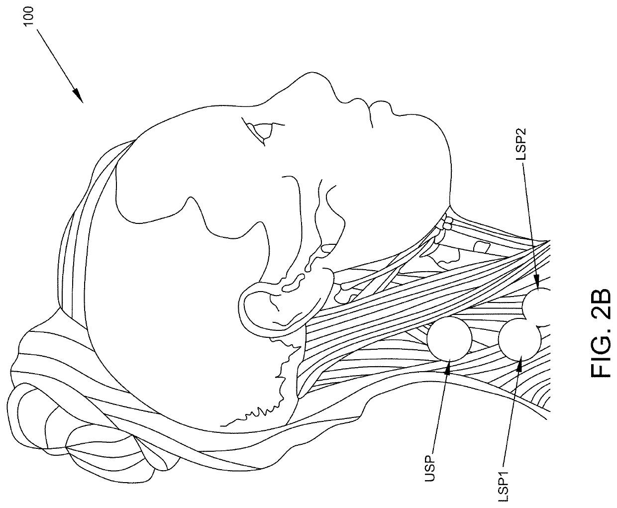
[0030]With reference to the Figures, where like elements have been given like numerical designations to facilitate an understanding of the drawings, the various embodiments of systems and computer-implemented methods of automated physiological monitoring, triage, and treatment are described. The figures are not drawn to scale.
[0031]Various embodiments address the foregoing deficiencies of prior art systems and methods of monitoring a person's physiological signs and analyzing such information for triage and treatment, especially in trauma, battlefield, emergency room, terrorist attack, or natural disaster scenarios including a pandemic, and provide systems and methods to facilitate dynamic, automatic, real-time prognoses and triage prioritization in such environments to the benefit of government, military, business, individual users (e.g., first responders, emergency medical technicians (EMTs)), patients, and providers of such services, alike. For example, patients benefit from bein...
PUM
Abstract
Physiological sign monitoring devices, and systems and computer-implemented methods of remote physiological monitoring of subjects. A monitoring device includes a plurality of physiological sign monitoring portions. Each physiological sign monitoring portion of the device is configured for deployment on a different, respective surface of a subject including a surface on the back of an ear of the subject, a surface over a mastoid region of the neck of the subject, and a surface over another region of the neck of the subject. Each physiological sign monitoring portion of the device includes a plurality of physiological sensors, where each sensor is configured to generate a respective electronic signal based on a respective monitored physiological parameter of the subject. At least one physiological sensor in each physiological sign monitoring portion of the device is configured to generate a respective electronic signal based on the same monitored physiological parameter of the subject.
Description
CROSS-REFERENCE TO RELATED APPLICATIONS[0001]This application is a continuation-in-part application of and claims priority to U.S. patent application Ser. No. 16 / 593,354, filed on Oct. 4, 2019, the entirety of which is herein incorporated by reference, which is a continuation-in-part application of and claims priority to U.S. patent application Ser. No. 15 / 889,992, filed on Feb. 6, 2018, the entirety of which is herein incorporated by reference, which claimed priority to U.S. patent application Ser. No. 14 / 812,696, filed on Jul. 29, 2015, the entirety of which is herein incorporated by reference, which claimed priority to U.S. Provisional Patent Application Ser. No. 62 / 030,314, filed on Jul. 29, 2014, and to U.S. Provisional Patent Application Ser. No. 62 / 081,185, filed on Nov. 18, 2014, the entirety of which are herein incorporated by reference.FIELD[0002]The present disclosure is directed generally to monitoring and analyzing data and more particularly to enhanced physiological mo...
Claims
Application Information
Patent Timeline
Application Date:The date an application was filed.
Publication Date:The date a patent or application was officially published.
First Publication Date:The earliest publication date of a patent with the same application number.
Issue Date:Publication date of the patent grant document.
PCT Entry Date:The Entry date of PCT National Phase.
Estimated Expiry Date:The statutory expiry date of a patent right according to the Patent Law, and it is the longest term of protection that the patent right can achieve without the termination of the patent right due to other reasons(Term extension factor has been taken into account ).
Invalid Date:Actual expiry date is based on effective date or publication date of legal transaction data of invalid patent.
Patent Type & Authority Applications(United States)