Adjustable multi-section blade structure for automatic planer

a multi-section, automatic planer technology, applied in the direction of flat surfacing machines, woodworking apparatus, manufacturing tools, etc., can solve the problems of large cutting load, inability to achieve blade precision after, blade dullness, etc., to reduce unnecessary waste, reduce cutting load, and maintain blade precision

Inactive Publication Date: 2021-01-14
CHUANG BOR YANN
View PDF0 Cites 1 Cited by
  • Summary
  • Abstract
  • Description
  • Claims
  • Application Information

AI Technical Summary

Benefits of technology

[0006]As to the adjustable multi-section blade structure for the automatic planer provided by the present invention, the cutters are spaced apart from each other and disposed along the axis of the cutter shaft to reduce the cutting load. After the blade is sharpened, it ca

Problems solved by technology

However, when the automatic planer is used for cutting, the cutting load is large because the blade of the cutter holder is in the form of a whole piece.
The precision of the blade cannot be achieved after the bla

Method used


Image

  • Adjustable multi-section blade structure for automatic planer
  • Adjustable multi-section blade structure for automatic planer
  • Adjustable multi-section blade structure for automatic planer

Examples


Embodiment Construction

[0014]Embodiments of the present invention will now be described, by way of example only, with reference to the accompanying drawings.

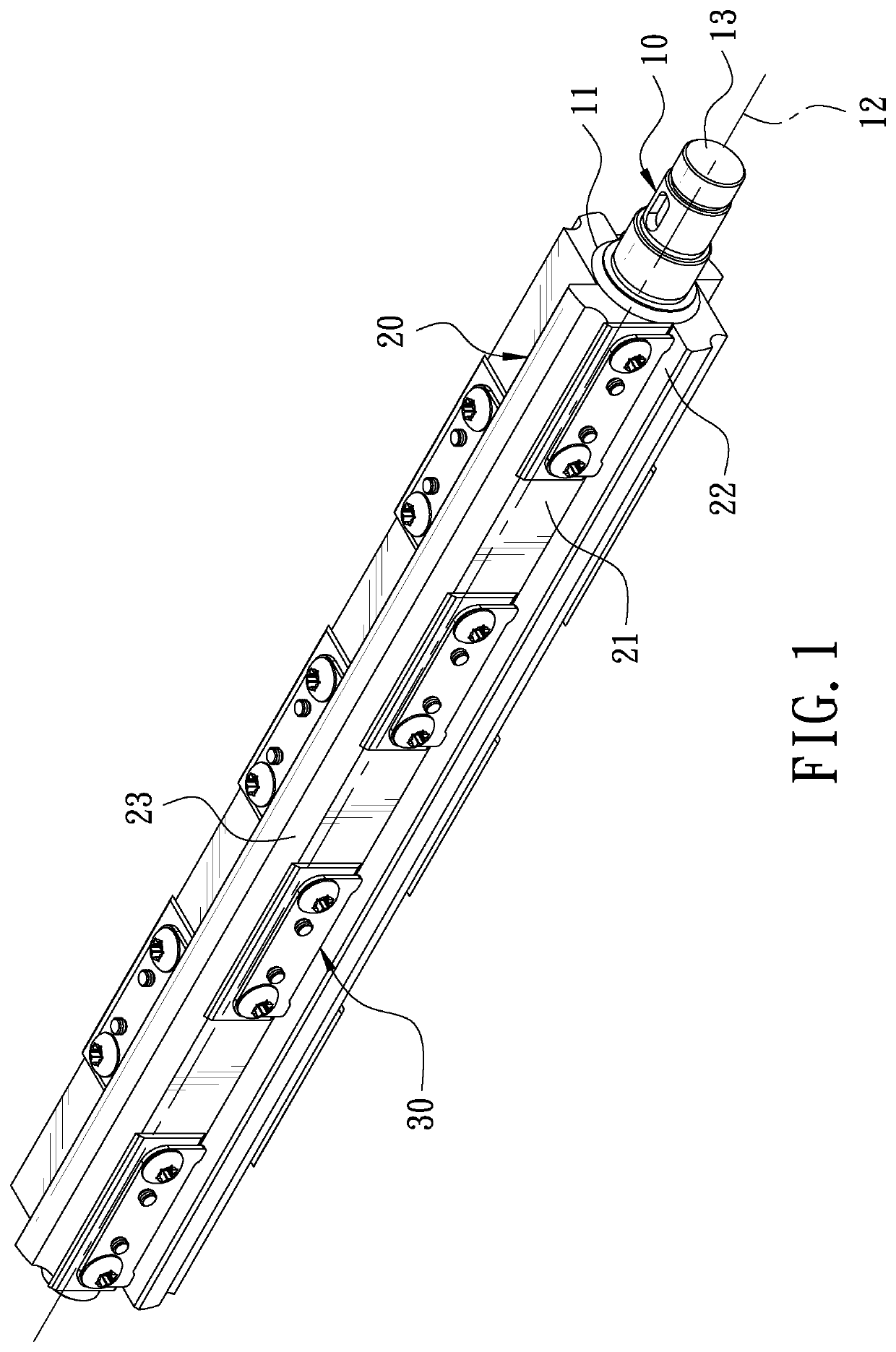
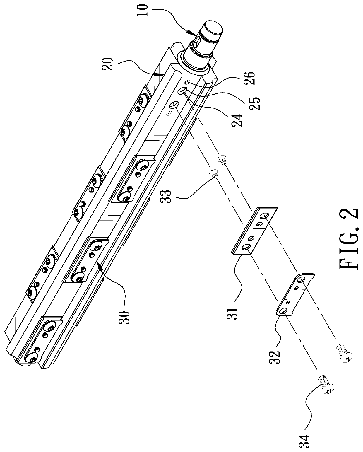
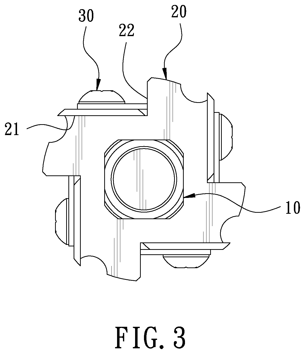
[0015]FIG. 1 is a perspective view in accordance with a preferred embodiment of the present invention. FIG. 2 is a partial exploded view in accordance with the preferred embodiment of the present invention. FIG. 4 is an exploded view of a blade calibration tool when in use in accordance with the preferred embodiment of the present invention. The present invention discloses an adjustable multi-section blade structure for an automatic planer, comprising a cutter shaft 10, a plurality of cutter holders 20, a plurality of cutters 30, and a blade calibration tool 40.

[0016]The cutter shaft 10 is a long cylinder. The cutter shaft 10 has an outer annular surface 11 and an axis 12. Either end of the cutter shaft 10 is provided with a transmission rod 13.

[0017]In this embodiment of the present invention, the number of the cutter holders 20 is four. The cutter h...


PUM


Abstract

An adjustable multi-section blade structure for an automatic planer includes a cutter shaft, a plurality of cutter holders, a plurality of cutters, and a blade calibration tool. The cutter shaft is a long cylinder. The cutter shaft has an outer annular surface and an axis. The cutter holders are arranged at substantially equiangular intervals around the outer annular surface of the cutter shaft. The cutter holders each have a fixing surface, a bearing surface, and an arcuate groove. The cutters are spaced apart from each other and disposed on the fixing surface. In addition to reducing the cutting load, the precision of the blade can be calibrated through the blade calibration tool to achieve an energy-saving effect.

Description

FIELD OF THE INVENTION[0001]The present invention relates to a blade structure for an automatic planer, and more particularly to an adjustable multi-section blade structure for an automatic planer.BACKGROUND OF THE INVENTION[0002]The cutter shaft structure of a conventional automatic planer includes a cutter shaft, a plurality of blades, and a plurality of cutter holders. The cutter shaft has an outer annular surface. The cutter holders are disposed at substantially equiangular intervals around the outer annular surface of the cutter shaft. Each blade is locked to a corresponding cutter holder by a plurality of positioning pins. The precision of the blade is maintained by the positioning pins, and the length of the blade is always the same as the length of the cutter holder.[0003]However, when the automatic planer is used for cutting, the cutting load is large because the blade of the cutter holder is in the form of a whole piece. When the machine is rotated at a high speed, the mac...

Claims


Application Information

Patent Timeline
IPC IPC(8): B27C1/14
CPCB27C1/14B27C1/02B27G13/02B27G13/04
Inventor CHUANG, BOR-YANN
Owner CHUANG BOR YANN
Why Eureka
Try Eureka