Height adjustment apparatus for a can body

a technology of height adjustment and can body, which is applied in the direction of shearing apparatus, other domestic objects, manufacturing tools, etc., to achieve the effects of reducing the cutting load applied to open the annular scrap remaining around the mandrel, and reducing the cutting load

Active Publication Date: 2017-07-11
DAIWA CAN
View PDF11 Cites 0 Cited by
  • Summary
  • Abstract
  • Description
  • Claims
  • Application Information

AI Technical Summary

Benefits of technology

[0007]The present invention has been conceived nothing the foregoing technical problems, and it is therefore an object of the present invention is to provide a height adjustment apparatus for a can body that can reduce a load applied to the apparatus during trimming of can bodies.
[0011]Thus, the height adjustment apparatus according to the present invention, a plurality of outer blades are arranged around the revolution orbit of the mandrels to trim the opening end of the can body together with the inner blades fitted onto each mandrel. In addition, the vertical reciprocator is adapted to gradually change a level of the opening end of the can body with respect to the level at which the outer blade and the inner blade are situated from an upstream side toward a downstream side in a revolution direction of the mandrels. According to the present invention, therefore, the opening end of the can body can be trimmed plurality of times by those inner and outer blades to achieve a desired height of the can body during one revolution of the can body fitted onto the mandrel. In addition, the trimmed away scrap produced as a result of trimming the can body can be downsized, and a cutting load applied to open the annular scrap remaining around the mandrel can be reduced. Further, a trimming amount of the can body can be adjusted finely by manually adjusting a level of the vertical reciprocator. According to the present invention, therefore, can bodies other than standard shape may also be trimmed easily without requiring modification of the apparatus.
[0012]As described, the outer blades are situated at the same level around the revolution orbit of the mandrels, and the level of each inner blade fitted onto the mandrel is adjusted to the same level as the outer blades to be opposed thereto. According to the present invention, therefore, a load to trim the opening end of the can body is applied homogeneously to each mandrels and each pair of inner and outer blades at the same level. In addition, the can body is fitted onto the mandrel gradually deeply from the upstream side to the downstream side of the revolution direction of the mandrel so that the opening end of the can body is allowed to be trimmed gradually from the upstream side to the downstream side.
[0013]As also described, the cylindrical cam may be employed as the vertical reciprocator. According to the present invention, therefore, circular motion of the mandrel around the cylindrical cam can be converted easily into a reciprocating motion.

Problems solved by technology

However, if a large part of the can body is trimmed away by a single operation, a large cylindrical scrap would be produced and hence the can trimming apparatus and a main drive shaft would be subjected to a large load to cut the cylindrical scrap into a plate shape.

Method used


Image

  • Height adjustment apparatus for a can body
  • Height adjustment apparatus for a can body
  • Height adjustment apparatus for a can body

Examples


Embodiment Construction

)

[0023]Hereinafter, a preferred example of the height adjustment apparatus will be explained in more detail with reference to the accompanying drawings.

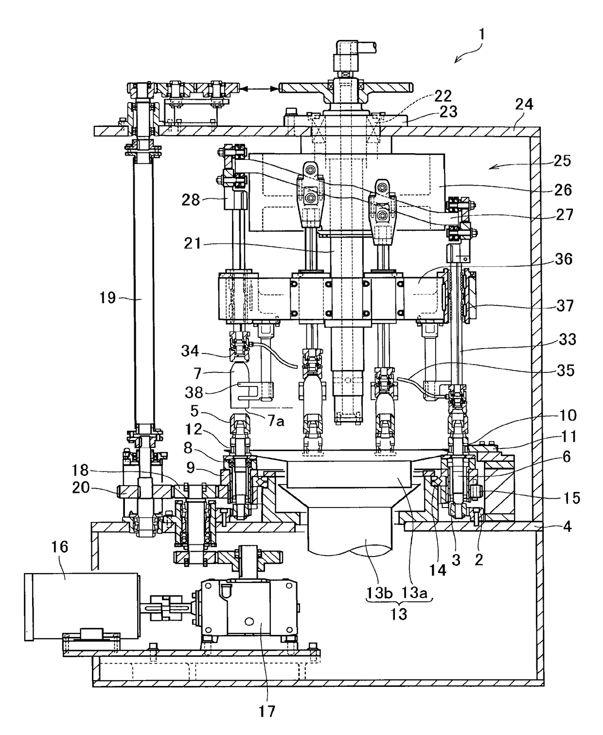
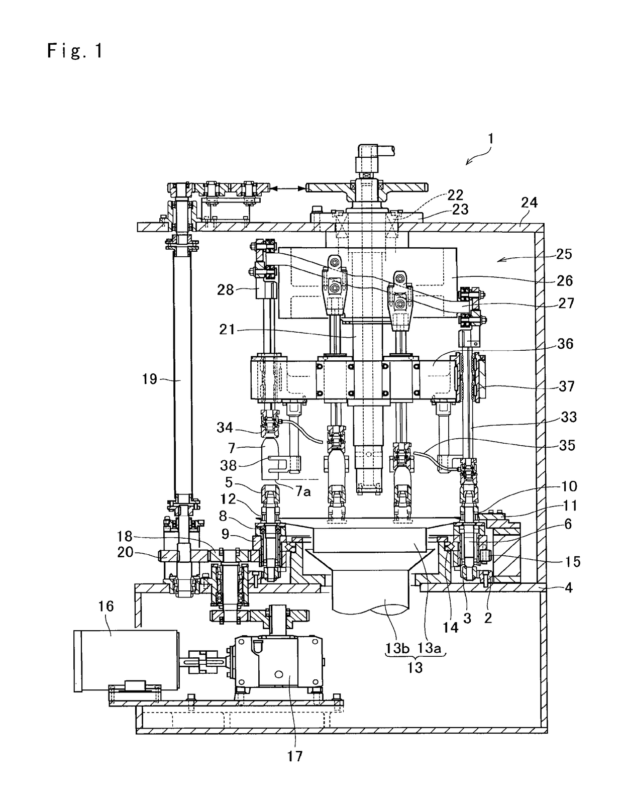
[0024]Referring now to FIG. 1, there is shown a cross-section of the height adjustment apparatus 1 according to the preferred example. The height adjustment apparatus is provided with a ring gear 2 as an internal gear that is attached to a lower frame 4. A plurality of pinion gears 3 are arranged along an inner circumference of the ring gear 2 at predetermined intervals while meshing therewith, and individually connected to each spindle shaft 6 of a mandrel 5 on which a can body 7 to be trimmed is mounted. Each pinion gear 3 revolves along the inner circumference of the ring gear 2, and consequently the mandrel 5 is rotated by a rotation of the pinion gear 3. Specifically, the can body 7 is allowed to be fitted onto the mandrel 5 until an inner face thereof comes into contact to a leading end of the mandrel 5. The can body 7 can be e...


PUM

PropertyMeasurementUnit
heightaaaaaaaaaa
heightaaaaaaaaaa
width sw1aaaaaaaaaa

Abstract

A height adjustment apparatus that can reduce a load to trim a can body is provided. The height adjustment apparatus 1 is adapted to adjust a height of a can body to a desired height by trimming one of opening ends of the can body. The height adjustment apparatus comprises: mandrels on which the can body is individually mounted and which revolve along a predetermined orbit while rotating; outer blades arranged around the revolution orbit of the mandrels; an inner blade fitted onto each mandrel to trim the opening end of the can body together with the outer blade; and a vertical reciprocator that gradually changes a level of the opening end of the can body with respect to a level at which the outer blade and the inner blade are situated from an upstream side toward a downstream side in a revolution direction of the mandrel.

Description

[0001]The present invention claims the benefit of Japanese Patent Application No.2014-183002 filed on Sep. 9, 2014 with the Japanese Patent Office, the disclosure of which is incorporated herein by reference in its entirety.BACKGROUND[0002]Field of the Invention[0003]The present invention relates to an art of an apparatus for adjusting a height of a can body by trimming an opening of the can body.[0004]Discussion of the Related Art[0005]JP-A-H4-505129 described an apparatus for use in trimming can bodies. The apparatus taught by JP-A-H4-505129 comprises a rotatable turret having a plurality of mounting surfaces that is secured to a main drive shaft, and a can trimming apparatus secured on the mounting surface of the turret. An uneven edge of the can body supported by a can body supporting means is trimmed to form a can body of the proper axial extent. A trimmed away portion from the can body is deflected by a scrap deflector.[0006]According to the teachings of JP-A-H4-505129, the un...

Claims


Application Information

Patent Timeline
Patent Type & Authority Patents(United States)
IPC IPC(8): B23D31/00B21D51/26
CPCB23D31/001B21D51/26
Inventor KAWAZOE, AKIRA
Owner DAIWA CAN
Why Eureka
Try Eureka