Optical coherence tomographic apparatus and optical coherence tomographic method

a tomographic apparatus and optical coherence technology, applied in the field of tomographic techniques, can solve problems such as image noise, and achieve the effect of optimal balan

Active Publication Date: 2021-01-14
DAINIPPON SCREEN MTG CO LTD
View PDF0 Cites 2 Cited by
  • Summary
  • Abstract
  • Description
  • Claims
  • Application Information

AI Technical Summary

Benefits of technology

[0017]As described above, according to the present invention, in an imaging technique employing optical coherence tomography, the center wavelength of a Gaussian distribution curve during spectrum conversion is shifted from the center wavelength of a light source spectrum. This achieves an optimum balance between a resolution and an imaging possible range in the depth direction.
[0018]The above and further objects and novel features of the invention will more fully appear from the following detailed description when the same is read in connection with the accompanying drawing. It is to be expressly understood, however, that the drawing is for purpose of illustration only and is not intended as a definition of the limits of the invention.

Problems solved by technology

According to the FD-OCT technique, if the spectrum of a light source differs from a Gaussian distribution, a side lobe appearing in a spectrum resulting from Fourier transform is known to cause image noise.

Method used


Image

  • Optical coherence tomographic apparatus and optical coherence tomographic method
  • Optical coherence tomographic apparatus and optical coherence tomographic method
  • Optical coherence tomographic apparatus and optical coherence tomographic method

Examples


Embodiment Construction

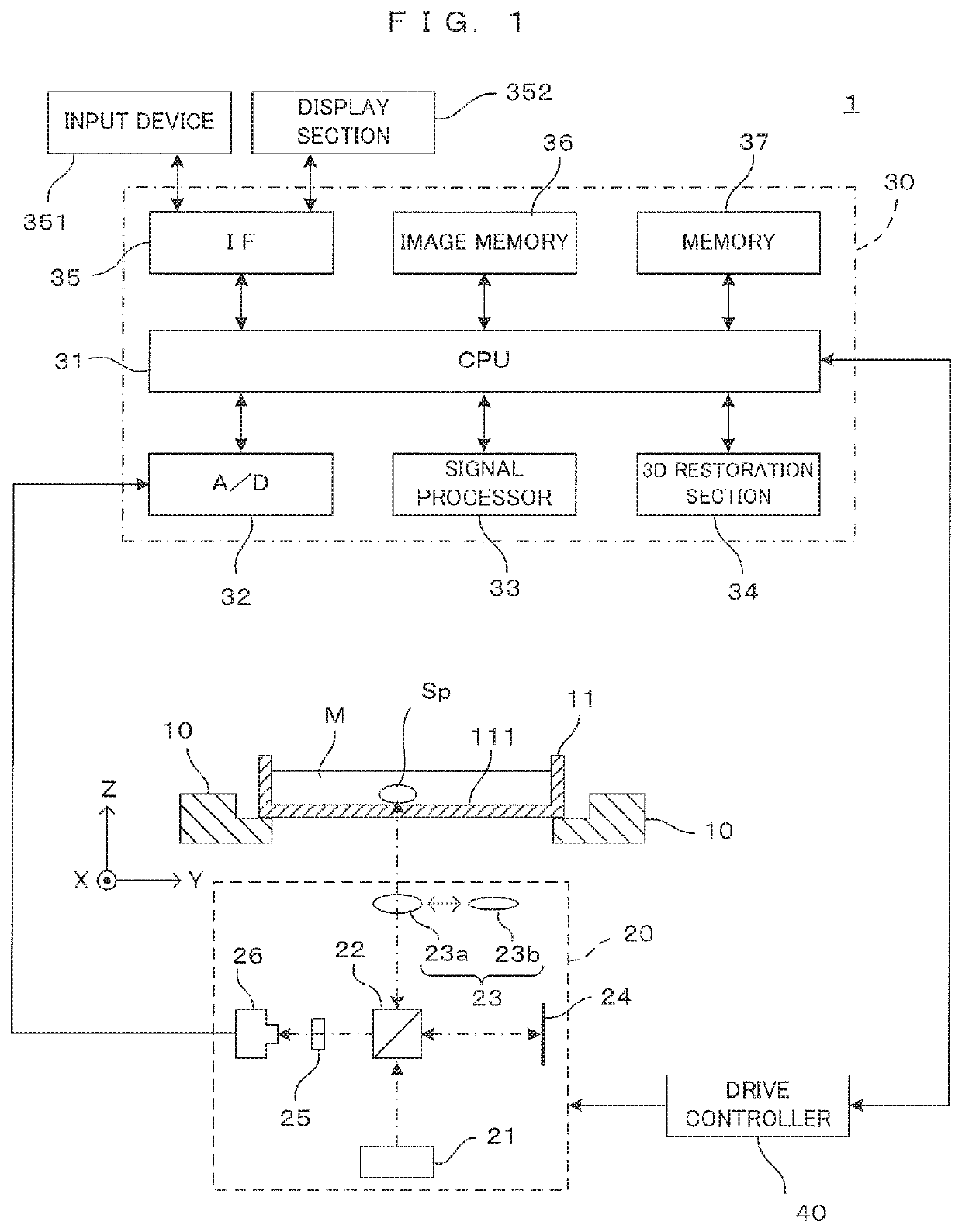
[0034]FIG. 1 is a drawing showing an embodiment of an imaging apparatus according to the present invention. The imaging apparatus 1 tomographically images a cell cultured in a culture medium M, a spheroid (cell aggregate) which consists of many cells, an organ-like structure (hereinafter, referred to as a “cell or the like” generically) as an imaging object, processes the obtained tomographic image and generates a stereoscopic image of the imaging object. Note that although an example of imaging a spheroid in the culture medium as the imaging object is illustrated here, the imaging object is not limited to this. For unified presentation of the directions in drawings, the XYZ orthogonal coordinate axes are established as shown in FIG. 1. The XY plane is a horizontal surface. The Z axis represents the vertical axis, in more detail, the (−Z) direction represents the vertically downward direction.

[0035]The imaging apparatus 1 comprises a holder 10. The holder 10 holds in an approximatel...


PUM

PropertyMeasurementUnit
wavelength rangeaaaaaaaaaa
optical coherence tomographic apparatusaaaaaaaaaa
spectrumaaaaaaaaaa

Abstract

To optimize an imaging range in a depth direction in terms of a relationship with a resolution, an OCT apparatus includes a signal processor that determines a reflected light intensity distribution of an imaging object on the basis of a spectrum of a detected interference light. The signal processor performs spectrum conversion, having a conversion characteristic with which a light source spectrum is converted to a Gaussian distribution curve, on the spectrum of the interference light, and determines the reflected light intensity distribution by Fourier-transforming a spectrum resulting from the spectrum conversion. In the conversion characteristic, the light source spectrum and the Gaussian distribution curve have center wavelengths differing from each other.

Description

TECHNICAL FIELD[0001]The present invention relates to a tomographic technique based on the principles of optical coherence tomographic imaging.BACKGROUND ART[0002]In technical fields of medical science and biochemistry, cells or microorganisms cultured in a container are observed. Techniques of imaging cells and the like to be observed using a microscope, for example, have been suggested as methods of observing such cells without affecting the cells. One of these techniques utilizes optical coherence tomography (hereinafter abbreviated as “OCT”) techniques. These OCT techniques include a technique called Fourier domain optical coherence tomography (hereinafter abbreviated as “FD-OCT”) by which light containing various types of wavelength components and emitted from a light source is caused to enter an imaging object, and interference light occurring between light reflected from the imaging object and reference light is detected. The spectrum of the interference light is Fourier-tran...

Claims


Application Information

Patent Timeline
Patent Type & Authority Applications(United States)
IPC IPC(8): G01B9/02G01N33/483G01N21/45
CPCG01B9/02091A61B5/0066G01N21/45G01N33/4833G01N21/4795G01N15/1434G01N2015/1445G01N15/1429G01N2015/1006G01N2015/1454G01N2015/1447G01N15/1463G01B9/02007G01B9/02044
Inventor ISHIKAWA, NAOKI
Owner DAINIPPON SCREEN MTG CO LTD
Why Eureka
Try Eureka