Check patentability & draft patents in minutes with Patsnap Eureka AI!

Touch force sensor using inductive sensing and capacitive sensing and method of operating same

a capacitive sensing and touch technology, applied in the field of touch force sensors, can solve the problems of difficult to perform precise measurement, low accuracy, and considerable time-consuming measurement, and achieve the effects of reducing power consumption, shortening the operation time of inductive sensors, and increasing the precision and reliability of touch detection

Active Publication Date: 2021-01-21
DAMOATECH CO LTD
View PDF0 Cites 12 Cited by
  • Summary
  • Abstract
  • Description
  • Claims
  • Application Information

AI Technical Summary

Benefits of technology

The patent describes various techniques to enhance the sensitivity of a sensor by adding a part or material and selecting the best combination of parts or materials. These techniques involve combining an inductive sensor with another sensor to detect touch force and location separately. Additionally, multiple inductive sensors can be used to recognize a user's gesture pattern by tracking the detection information.

Problems solved by technology

Due to this configuration, the conventional technologies have problems in that there occurs an error corresponding to the resolution of the variable frequency of an input electric signal, accuracy is low due to the indirect method of detecting the magnitude of an electrical signal and calculating a resonant frequency, and measurement takes a considerably long time because the frequency of an input electric signal needs to be varied.
Furthermore, the conventional technologies have difficulty in performing precise measurement because they calculate a resonant frequency and an inductance by detecting the magnitude of an electric signal, and thus they mainly determine whether a change in inductance exceeds a specific threshold value, but does not provide sufficient accuracy to quantitatively analyze changes in inductance.

Method used


Image

  • Touch force sensor using inductive sensing and capacitive sensing and method of operating same
  • Touch force sensor using inductive sensing and capacitive sensing and method of operating same
  • Touch force sensor using inductive sensing and capacitive sensing and method of operating same

Examples


Embodiment Construction

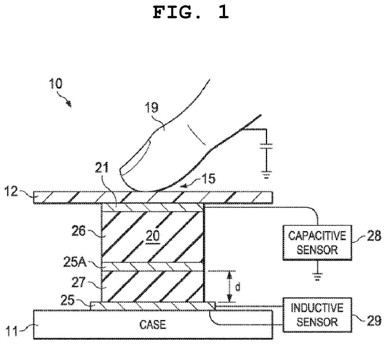
[0064]Other objects and features of the present invention in addition to the above objects will be apparent from the following description of embodiments with reference to the accompanying drawings. Embodiments of the present invention will be described in detail below with reference to the accompanying drawings. In the following description, when it is determined that a detailed description of a related known component or function may unnecessarily make the gist of the present invention obscure, it will be omitted. A touch force sensor and a method of operating the same according to embodiments of the present invention will be described in detail below with reference to FIGS. 1 to 17.

[0065]In place of a capacitive proximity sensor, an inductive touch sensor has been proposed to measure inductance by causing a change in the magnetic field in a manner to recognize touch pressure by measuring a change in impedance. The fact that an inductive sensor is not sensitive to an external dist...


PUM


Abstract

A touch force sensor includes a reference resonant circuit, a first resonant circuit coupled to an inductive coil, a second resonant circuit connected to a touch electrode, and further includes a determination circuit configured to obtain a first resonant frequency attributable to a first inductance formed in an inductive coil and a first resonant circuit based on a displacement between a target and the inductive coil formed by an external force input in a Z-axis direction, the second resonant frequency of a second resonant circuit attributable to a capacitance varying depending on whether a finger comes into contact with the touch electrode, and information about a reference resonant frequency.

Description

CROSS-REFERENCE TO RELATED APPLICATION[0001]This application claims the priority from Korean Patent Application No. 10-2019-0086776 filed on Jul. 18, 2019, which is incorporated herein by reference in its entirety.TECHNICAL FIELD[0002]The present invention relates generally to a touch force sensor and a method of operating the same, and more particularly to a touch force sensor that detects the degree of force by using inductance varying depending on a change in the distance between a target layer and a coil, formed on a printed circuit board (PCB) or flexible PCB (FBCB) or as a transparent electrode, attributable to external force, and a method of operating the same.[0003]The present invention was derived from the research conducted as part of the Start-up Leaping Package Support Project sponsored by the Korean Ministry of SMEs and Startups and the Korea Institute of Startup & Entrepreneurship Development [Project Management No.: 10221619; and Project Name: Development of Force Sen...

Claims


Application Information

Patent Timeline
IPC IPC(8): G06F3/041G01D5/20G06F3/046G06F3/044G01D5/24
CPCG06F3/0414G01D5/2006G01D5/24G06F3/044G06F3/046G06F2203/04105G06F2203/04108G06F3/0416H03K17/962
Inventor JUNG, HU MIN
Owner DAMOATECH CO LTD
Features
  • R&D
  • Intellectual Property
  • Life Sciences
  • Materials
  • Tech Scout
  • Unparalleled Data Quality
  • Higher Quality Content
  • 60% Fewer Hallucinations
Learn More