Vibration nozzle for bidet

a technology of vibration nozzle and bidet, which is applied in the direction of spray nozzle, water installation, construction, etc., can solve the problems of user discomfort, parts to be washed may not be effectively washed, and parts that cannot be effectively washed, so as to reduce the size of the nozzle tip, improve the reliability of a product, and maximize the vibration efficiency

Pending Publication Date: 2021-01-28
LIM YOUNG KYOUN
View PDF0 Cites 1 Cited by
  • Summary
  • Abstract
  • Description
  • Claims
  • Application Information

AI Technical Summary

Benefits of technology

[0025]A vibration nozzle for a bidet according to the present disclosure is advantageous in that a nozzle tip and a vibration motor are formed to be separate, so that the nozzle tip has maximized vibration efficiency, thus allowing a user's body part to be washed cleanly and thereby improving the reliability of a product.
[0026]Furthermore, a vibration nozzle for a bidet according to the present disclosure is advantageous in that a nozzle tip is coupled only to a part of the inside of the front end of a nozzle cover so as to reduce the size of the nozzle tip, thus reducing manufacturing costs and thereby securing economic efficiency.
[0027]Furthermore, a vibration nozzle for a bidet according to the present disclosure is advantageous in that washing-water supply tubes connected to a nozzle tip are arranged at both sides of a shaft of a vibration motor such that the diameter of a nozzle can be minimized and a structure for forming a separate water channel is unnecessary, and thus manufacturing costs can be remarkably reduced.

Problems solved by technology

However, the nozzle provided to be used for washing is problematic in that washing water discharged through a washing-water tank in the bidet is directly discharged through a wash hole, so that a part to be washed may not be effectively washed.
However, the discharge tip structure is problematic in that a certain amount of washing water is intermittently discharged, so that a user may feel pain due to the water pressure of the washing water and may feel uncomfortable.
However, the vibration device is problematic in that the vibratory part is integrally mounted inside the nozzle, so that the vibrating amplitude of the nozzle is small and washing power is low, and the vibratory member for generating vibration in the nozzle is orthogonally or perpendicularly mounted to a nozzle tube, so that it is difficult to provide large movement to the stream of water discharged through a wash hole.

Method used


Image

  • Vibration nozzle for bidet
  • Vibration nozzle for bidet
  • Vibration nozzle for bidet

Examples


Embodiment Construction

[0033]Hereinafter, an embodiment of the present disclosure will be described in detail with reference to the accompanying drawings.

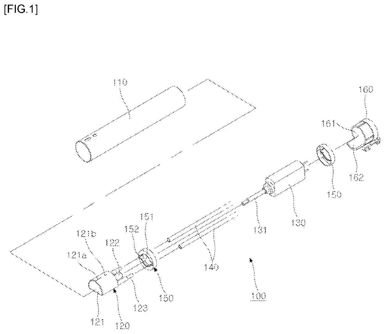
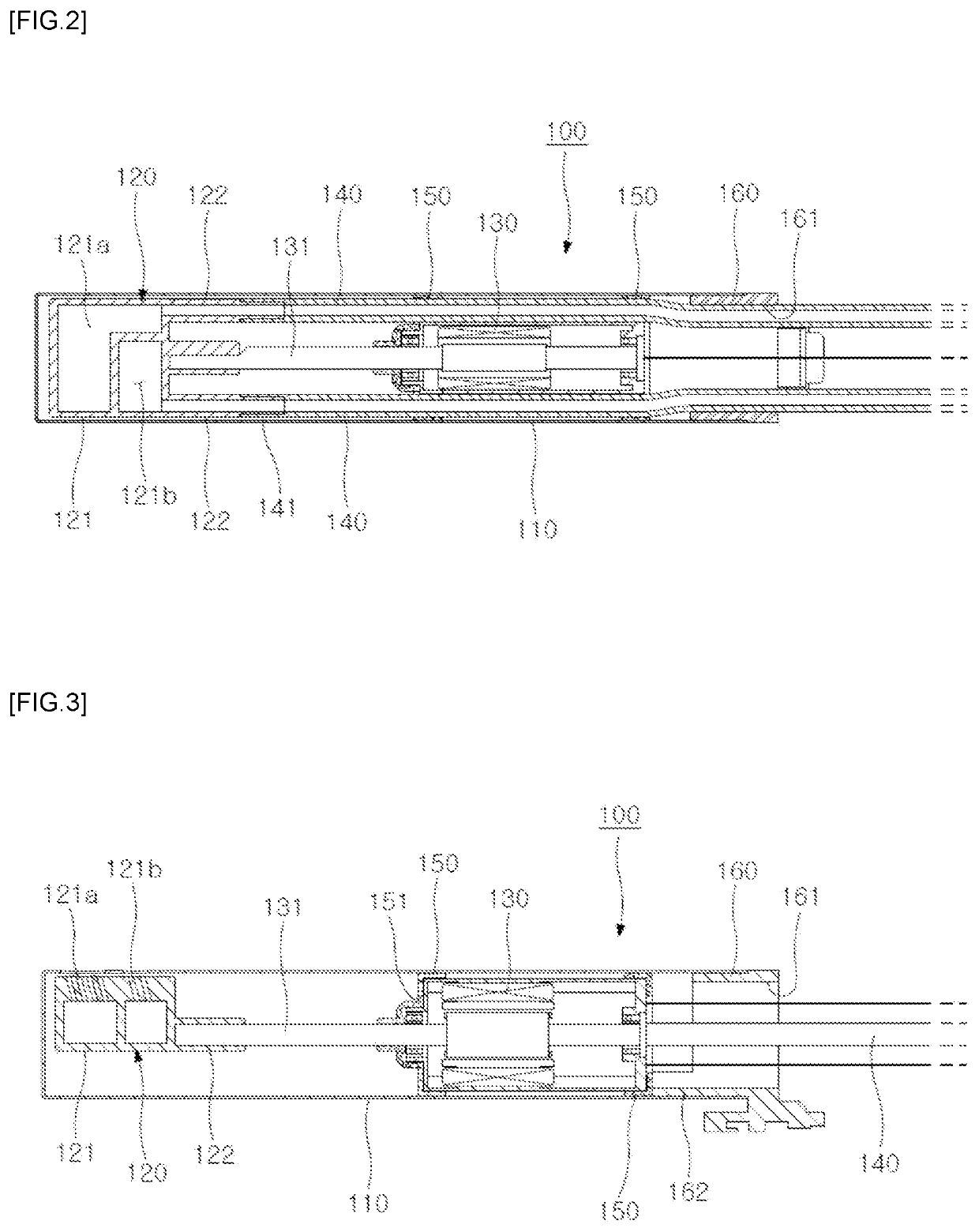
[0034]FIG. 1 is an exploded perspective view of the present disclosure, FIG. 2 is a plan sectional view of the present disclosure, and FIG. 3 is a side sectional view of the present disclosure.

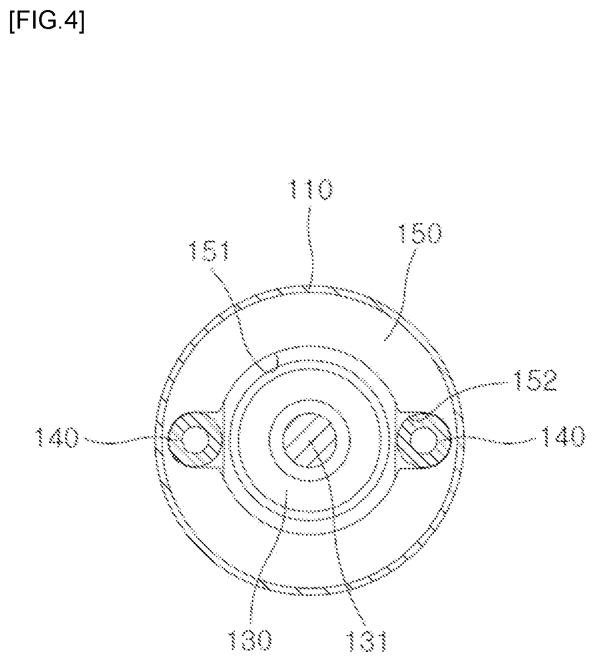
[0035]A vibration nozzle 100 for a bidet according to the present disclosure is composed of a nozzle cover 110, a nozzle tip 120, a vibration motor 130, washing-water supply tubes 140, vibration-proof members 150, and a closure cover 160, which will be described in detail below.

[0036]First, the nozzle cover 110 is formed to have a length accommodating the nozzle tip 120, the vibration motor 130, the washing-water supply tubes 140, and the vibration-proof members 150, and is preferably formed of a resin material or a stainless material.

[0037]Furthermore, the nozzle tip 120 is coupled to the front end of the nozzle cover 110, and is spaced apart from the vibration mo...


PUM


Abstract

Proposed is a vibration nozzle for a bidet, having a nozzle tip and a vibration motor that are formed to be separate such that the nozzle tip has maximized vibration efficiency so as to allow clean washing, the nozzle tip is coupled only to a part of the inside of the front end of a nozzle so as to be reduced in size, thereby having reduced manufacturing costs, and washing water supply pipes connected to the nozzle tip are arranged at both sides of the shaft of the vibration motor such that the diameter of the nozzle can be minimized and a structure for forming a separate water channel is unnecessary, and thus manufacturing costs can be reduced.

Description

CROSS-REFERENCE TO RELATED APPLICATIONS[0001]This application claims the benefit under 35 U.S.C. section 371, of PCT International Application No.: PCT / KR2019 / 001199, filed on Jan. 29, 2019, which claims foreign priority to Korean Patent Application No.: 10-2018-0041928, filed on Apr. 11, 2018, in the Korean Intellectual Property Office, both of which are hereby incorporated by reference in their entireties.TECHNICAL FIELD[0002]The present disclosure relates to a vibration nozzle for a bidet. More particularly, the present disclosure relates to a vibration nozzle for a bidet, in which a nozzle tip and a vibration motor are formed to be separate such that the nozzle tip has maximized vibration efficiency so as to allow clean washing, the nozzle tip is coupled only to a part of the inside of the front end of a nozzle cover so as to be reduced in size thereby reducing manufacturing costs, and washing-water supply tubes connected to the nozzle tip are arranged at both sides of a shaft o...

Claims


Application Information

Patent Timeline
Patent Type & Authority Applications(United States)
IPC IPC(8): B05B17/06E03D9/08
CPCB05B17/0623E03D9/08B05B1/16B05B1/18B05B17/0607
Inventor LIM, YOUNG KYOUN
Owner LIM YOUNG KYOUN
Why Eureka
Try Eureka