

Reference voltage circuit
a reference voltage and circuit technology, applied in the direction of instruments, amplifiers with semiconductor devices only, etc., can solve the problem of difficult power consumption reduction of the reference voltage circuit, and achieve the effect of saving power and reducing power consumption
- Summary
- Abstract
- Description
- Claims
- Application Information
AI Technical Summary
Benefits of technology
Problems solved by technology
Method used
Image

Examples
first embodiment
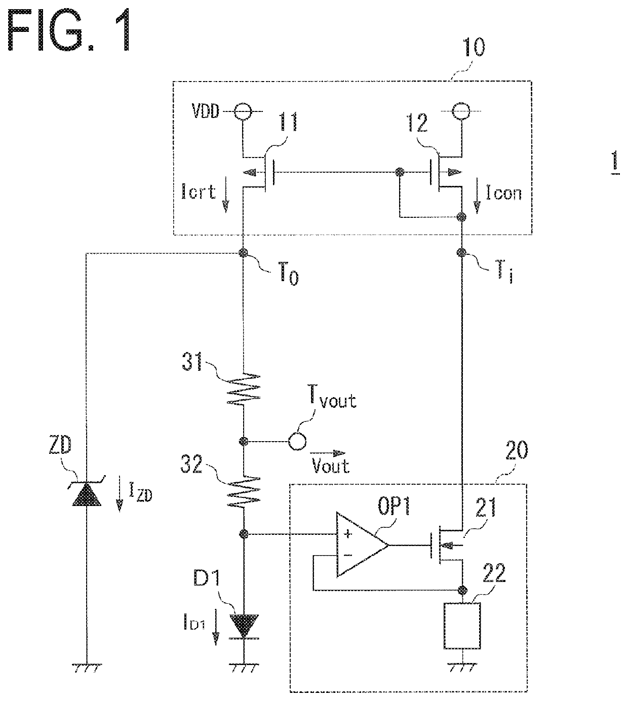
[0028]FIG. 1 is a circuit diagram illustrating a configuration example of a reference voltage circuit according to the first embodiment of the present invention.
[0029]A reference voltage circuit 1 includes a current mirror circuit 10, a current control circuit 20, a resistor 31 (first resistor), a resistor 32 (second resistor), a Zener diode ZD, and a diode D1.
[0030]The current mirror circuit 10 includes p-channel transistors 11 and 12. A drain of the transistor 11 is connected to an output terminal To, and a drain of the transistor 12 is connected to an input terminal Ti.
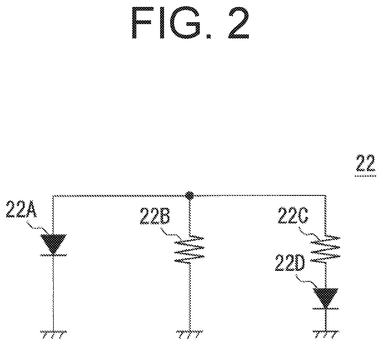
[0031]The current control circuit 20 is a current source in the reference voltage circuit 1, and includes an error amplifier circuit OP1, a transistor 21, and a V / I conversion element 22.
[0032]The Zener diode ZD has a cathode connected to the output terminal To of the current mirror circuit 10, and an anode connected to the ground point.
[0033]The resistor 31 has one end connected to the cathode of the Zener diode ...
second embodiment
[0071]FIG. 4 is a circuit diagram illustrating a configuration example of a reference voltage circuit according to the second embodiment of the present invention.
[0072]A reference voltage circuit 1A includes a current source 10A, a current control circuit 20A, resistors 31 and 32, a Zener diode ZD, and a diode D1.
[0073]The current source 10A includes a p-channel transistor 13.
[0074]The current control circuit 20A includes an error amplifier circuit OP2, a V / I conversion element 22, and a transistor 23.
[0075]The transistor 13 includes a source to which a power supply voltage VDD is applied, a gate connected to the output terminal of the error amplifier circuit OP2 and the gate of the transistor 23, and a drain connected to the cathode of the Zener diode ZD and one end of the resistor 31.
[0076]The transistor 23 is a p-channel transistor. The transistor 23 includes a source to which the power supply voltage VDD is applied, and a drain connected to one end of the V / I conversion element...
third embodiment
[0088]FIG. 5 is a circuit diagram illustrating a configuration example of a reference voltage circuit according to the third embodiment of the present invention.
[0089]A reference voltage circuit 1B has a configuration similar to that of the second embodiment except that the reference voltage circuit 1B includes a current control circuit 20B.
[0090]The current control circuit 20B includes p-channel transistors 24 and 25, n-channel transistors 26 and 27, and a V / I conversion element 22.
[0091]The transistor 24 includes a source to which the power supply voltage VDD is applied, a gate connected to the gate and the drain of the transistor 25, and a drain connected to the drain and the gate of the transistor 26.
[0092]The transistor 25 includes a source to which the power supply voltage VDD is applied, and the drain connected to the drain of the transistor 27.
[0093]The transistor 26 includes the gate connected to the gate of the transistor 27, and a source connected to the anode of the diod...
PUM
 Abstract
Description
Claims
Application Information