First Embodiment
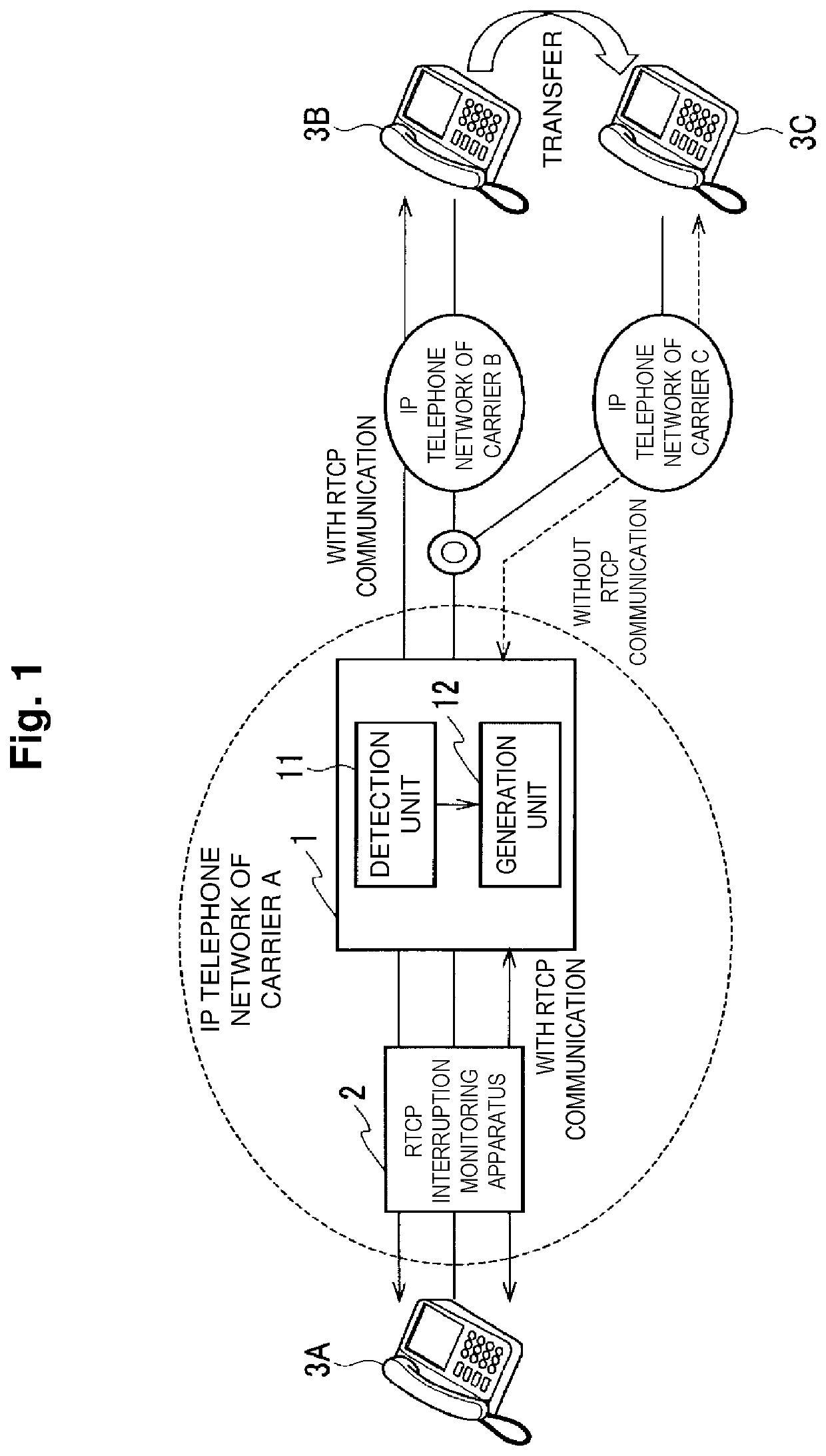
[0027]FIG. 1 is an overall configuration diagram including a gateway device in a first embodiment. In an IP phone network of a carrier A, a gateway device 1 installed on a POI (Point Of Interface) among IP phone networks of carriers A, B and C, and an RTCP interruption monitoring device 2 that performs interruption monitoring of RTCP.
[0028]The gateway device 1 is provided with a detection unit 11 and a generation unit 12. Each unit that the gateway device 1 is provided with may be configured with a computer provided with a processor, a storage device and the like, and a process of each unit may be executed by a program. This program is stored in the storage device that the gateway device 1 is provided with, and it is also possible to record the program to a recording medium such as a magnetic disk, an optical disk and a semiconductor memory or provide the program through a network.
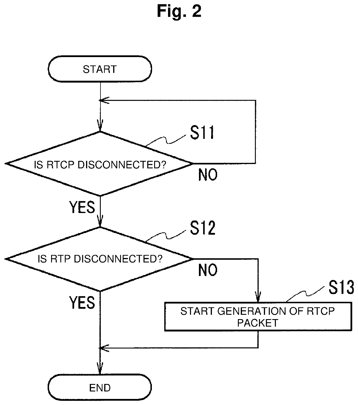
[0029]For certain communication, the detection unit 11 starts monitoring of RTP/RTCP packets, being triggered by reception of the first RTCP packet, and detects that RTCP packet sending-out conditions have been changed. Specifically, in the case of continuously receiving RTP packets even after reception of RTCP packets is stopped, the detection unit 11 determines that the RTCP packet sending-out conditions have been changed, and that the communication is continued.
[0030]When the RTCP packet sending-out conditions have been changed, and sending-out of RTCP is stopped, the generation unit 12 starts generation and sending-out of RTCP packets. The generation unit 12 can generate RTCP packets based on received RTP packets.
[0031]Next, an operation of the gateway device 1 will be described.
[0032]FIG. 2 is a flowchart showing a flow of a process of the gateway device 1. The gateway device 1 starts the process of FIG. 2, being triggered by reception of the first RTCP packet.
[0033]The detection unit 11 monitors RTCP packets that the gateway device 1 relays, and determines whether RTCP packets are received or not (step S11).
[0034]If RTCP packets are received (step S11: NO), the detection unit 11 continues monitoring of RTCP packets.
[0035]When reception of RTCP packets is stopped (step S11: YES), the detection unit 11 determines whether RTP packets are continuously received or not (step S12).
[0036]If RTP packets are continuously received (step S12: NO), the generation unit 12 starts generation/sending-out of RTCP packets (step S13). The generation unit 12 generates and sends out an RTCP packet at a predetermined timing as far as RTP packets are continuously received.
[0037]If RTP packets are not continuously received (step S12: YES), it is determined that communication ends, and the process ends.
[0038]Next, a flow of an overall process will be described.
[0039]A description will be made on an example where, in FIG. 1, a source terminal 3A accommodated in the IP phone network of the carrier A transmits a request to a destination terminal 3B accommodated in the IP phone network of the carrier B, and the IP phone network of the carrier B that receives the request transfers the request to a transfer destination terminal 3C accommodated in the IP phone network of the carrier C.
[0040]The request transmitted from the source terminal 3A is transmitted to the IP phone network of the carrier B accommodating the destination terminal 3B. An AS of the carrier B that receives the request gives voice guidance to the effect that the call is transferred to the source terminal 3A. At this time, media including RTP/RTCP are sent out as the voice guidance from the AS of the carrier B to the source terminal 3A.
[0041]The gateway device 1 and the RTCP interruption monitoring device 2 starts RTCP interruption monitoring, being triggered by reception of the first RTCP packet from the AS of the carrier B. The gateway device 1 also performs interruption monitoring for RTP packets.
[0042]The AS of the carrier B generates a new request and sends out the new request to the transfer destination terminal 3C to transfer the incoming call from the source terminal 3A to the transfer destination terminal 3C.
[0043]When receiving the request, the transfer destination terminal 3C returns a response to the source terminal 3A, and communication is established between the source terminal 3A and the transfer destination terminal 3C. Note that the transfer destination terminal 3C is a terminal that does not send out RTCP packets here.
[0044]After the communication is established between the source terminal 3A and the transfer destination terminal 3C, RTP packets are transmitted and received between the source terminal 3A and the transfer destination terminal 3C, but the transfer destination terminal 3C stops sending-out of RTCP packets. As a result, reception of RTCP packets by the gateway device 1 and the RTCP interruption monitoring device 2 is stopped.
[0045]The gateway device 1 continuously receives RTP packets even after reception of RTCP packets is stopped. Therefore, determining that the U-plane and the terminals are not abnormal, the gateway device 1 generates RTCP packets and sends out the RTCP packets to the source terminal 3A side. Note that it is assumed that time required until start of generation of RTCP packets after detection of RTCP interruption by the gateway device 1 is shorter than the interruption monitoring timer of the RTCP interruption monitoring device 2.
[0046]Though the transfer destination terminal 3C does not send out RTCP packets, the gateway device 1 generates and sends out RTCP packets. Therefore, the communication between the source terminal 3A and the transfer destination terminal 3C is continued without the RTCP interruption monitoring device 2 detecting interruption.
[0047]The gateway device 1 generates and sends out RTCP packet as far as it continuously receives RTP packets. When reception of RTP packets is stopped, the gateway device 1 ends generation of RTCP packets.