
Method and system for correcting errors in fueling commands

a fueling command and command technology, applied in the field of fueling systems, can solve the problems of actual fueling varying from its desired amount, unable to measure lambda during cranking, and typically unavailable lambda measurement during cranking, so as to eliminate or reduce the steady state error in lambda

Active Publication Date: 2021-02-11
CUMMINS INC
View PDF1 Cites 0 Cited by
  • Summary
  • Abstract
  • Description
  • Claims
  • Application Information

AI Technical Summary

Benefits of technology

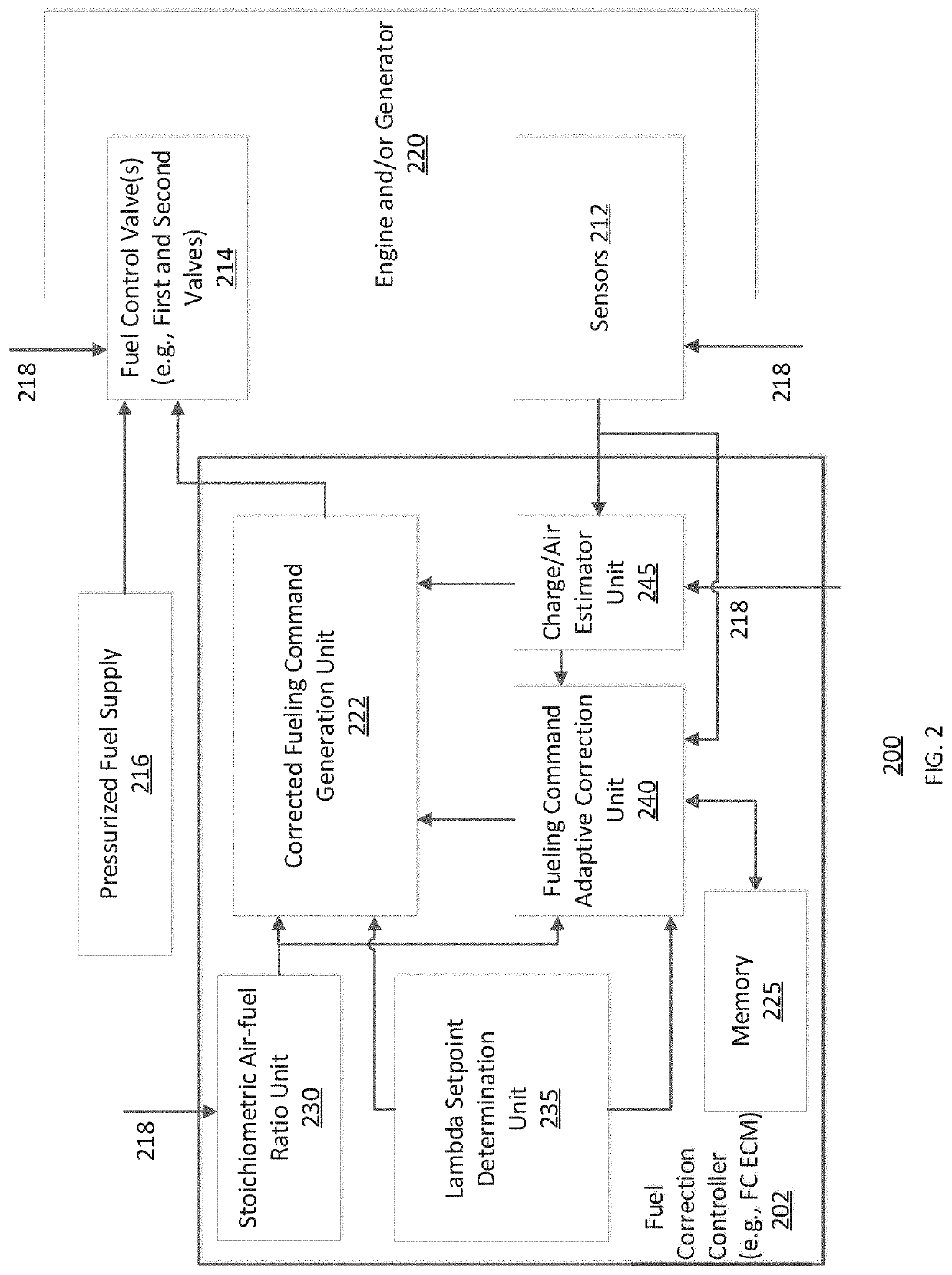
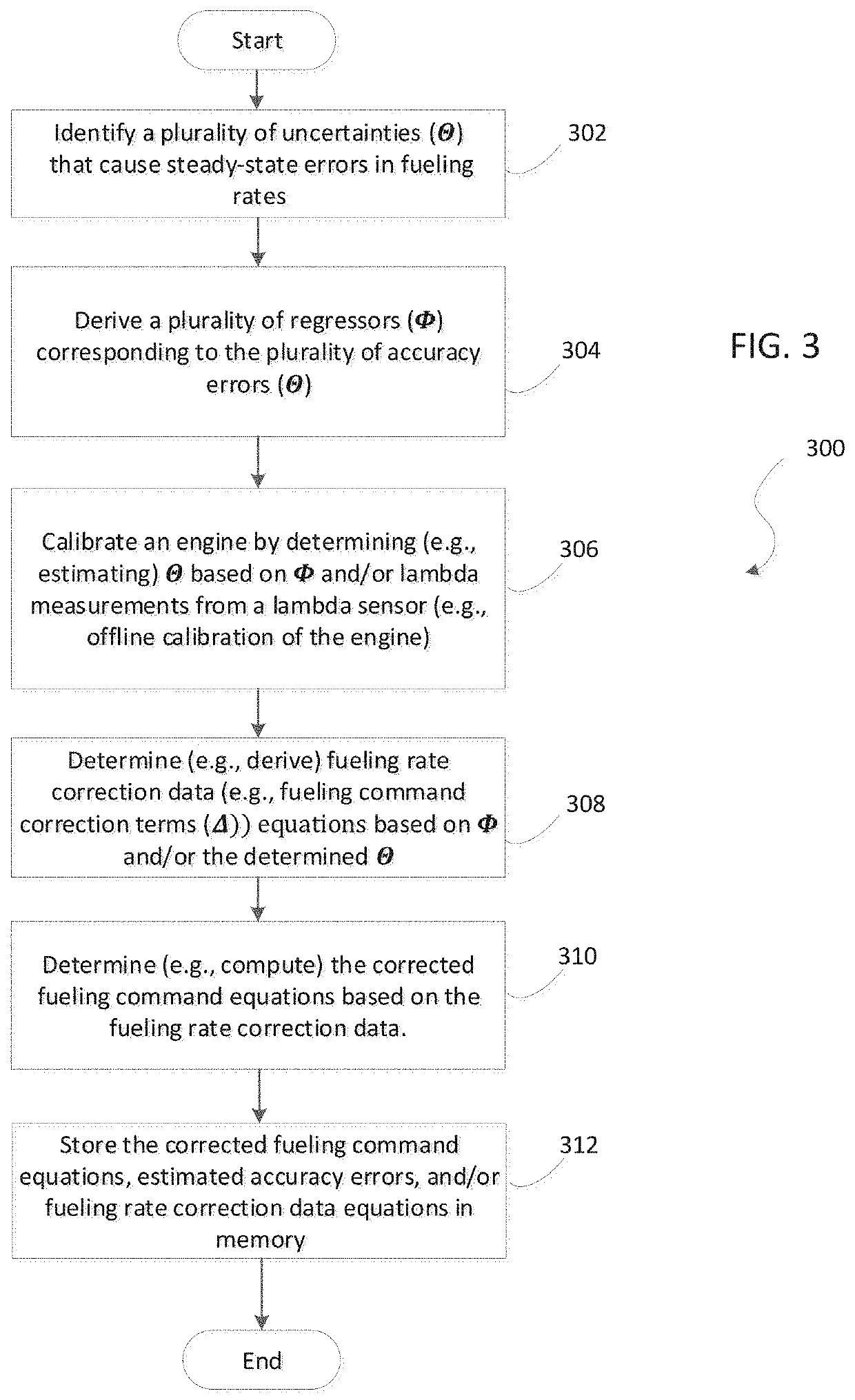
The patent describes a system that can determine corrected fueling commands to compensate for errors in fueling caused by accuracy errors. These corrected fueling commands are used to control the fuel valves within the system. The system can estimate the accuracy errors based on the determined fueling commands and sensor readings, and use them to effectively eliminate or reduce the steady state error in lambda induced by fueling accuracy errors even when lambda feedback is unavailable. The corrected fueling can be used for feed-forward lambda control scenarios or closed-loop lambda controls to improve transient performance.

Problems solved by technology

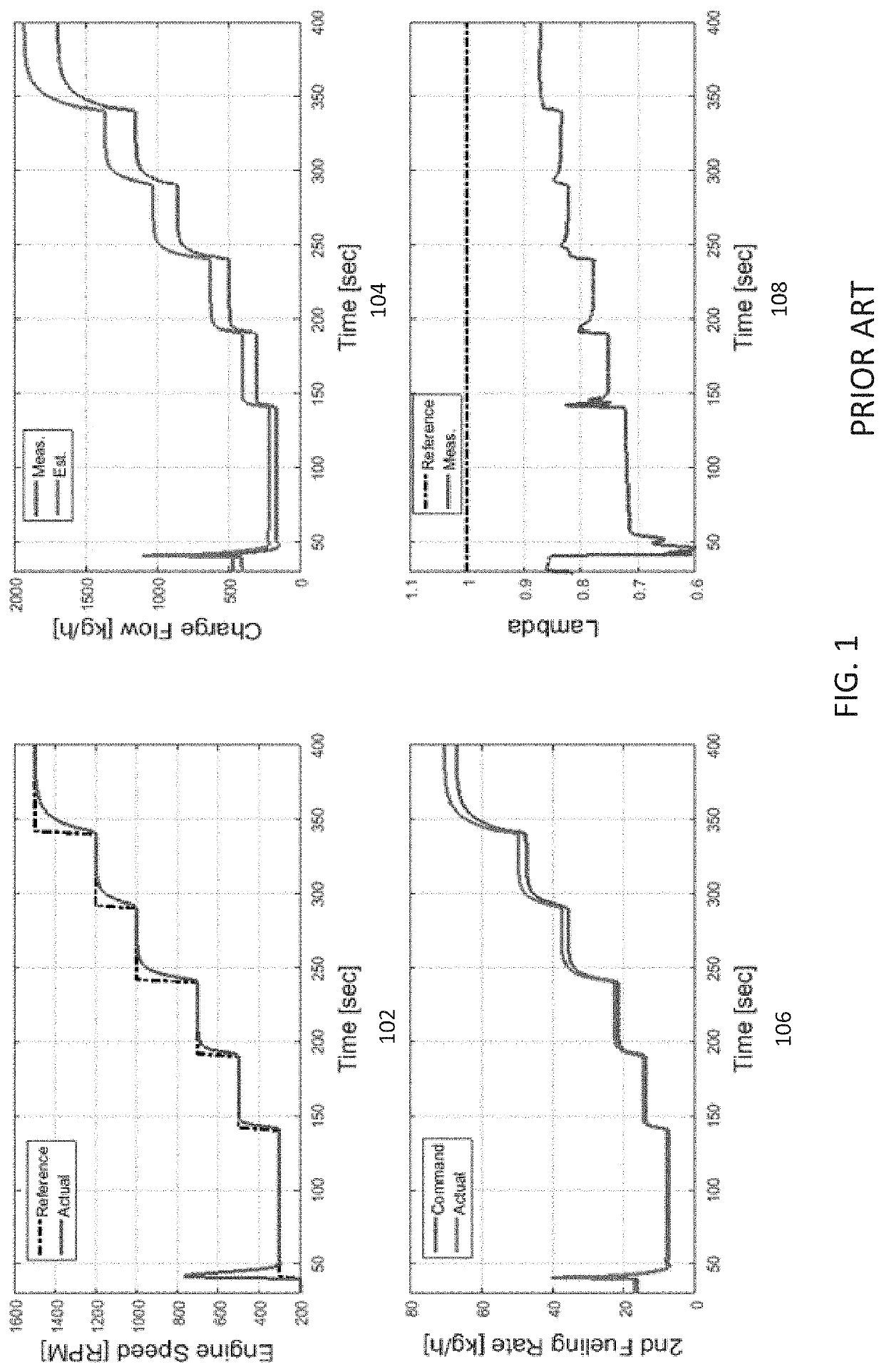
However, uncertainties in generating fueling commands in various operating conditions as well as uncertainties in the fuel system, and other factors may result in actual fueling varying from its desired amount.
However, in some examples, the measurements from the lambda sensor may be unavailable and thus lambda control only relies on a feed-forward control manner.
For example, lambda measurements are typically unavailable during cranking (e.g., starting the engine) as the sensor requires time to warm up before it can provide an output.
As a result, the uncertainties in fueling may result in steady-state errors in lambda tracking, and thus either preventing the engine from starting on time or, in the worst case, not starting at all.

Method used


Image

  • Method and system for correcting errors in fueling commands
  • Method and system for correcting errors in fueling commands
  • Method and system for correcting errors in fueling commands

Examples


Embodiment Construction

[0029]In the following detailed description, reference is made to the accompanying drawings which form a part hereof, and in which is shown by way of illustration specific embodiments in which the present disclosure is practiced. These embodiments are described in sufficient detail to enable those skilled in the art to practice the present disclosure, and it is to be understood that other embodiments can be utilized and that structural changes can be made without departing from the scope of the present disclosure. Therefore, the following detailed description is not to be taken in a limiting sense, and the scope of the present disclosure is defined by the appended claims and their equivalents.

[0030]In the current state of the art, traditional fueling commands (e.g., nominal fueling commands) are determined based on the estimated charge / air flow rate, the stoichiometric air-fuel ratio, the lambda setpoint, etc., without considering fueling accuracy errors. For example, the relation b...


PUM


Abstract

A method and system is provided for correcting fueling commands. For example, the method and system may calibrate an engine operating in a steady-state mode by determining a plurality of accuracy errors associated with a fueling rate based on a plurality of sensor measurements. The method and system may determine fueling rate correction data during on-line operation of the engine based on the plurality of accuracy errors. The on-line operation of the engine may comprise operating the engine in a transient mode at a first period of time and a steady-state mode at a second period of time. The method and system may control at least one fueling valve during operation of the engine using a corrected fueling command. The corrected fueling command is based on the fueling rate correction data.

Description

CROSS-REFERENCE TO RELATED APPLICATIONS[0001]The present application claims priority to U.S. patent application Ser. No. 62 / 884,456, filed Aug. 8, 2019, the entire disclosure of which being expressly incorporated herein by reference.FIELD OF THE DISCLOSURE[0002]The present disclosure generally relates to fueling systems and more specifically to adjusting fueling commands to correct fueling rate errors.BACKGROUND OF THE DISCLOSURE[0003]In power generation systems, the engine combusts fuel provided by the fuel system using an oxidant, such as oxygen, to provide energy that drives the generator. Specifically, an engine controller (e.g., an electronic control module (ECM)) monitors a plurality of system operating parameters via various sensors and interprets a subset of the monitored parameters, such as engine speed, mass air flow rate, etc., to determine the fueling command that indicates desired amount of fuel to be injected. Fuel is then metered by the fuel system based on the fuelin...

Claims


Application Information

Patent Timeline
IPC IPC(8): F02D41/14F02D41/24F02D41/18
CPCF02D41/1402F02D41/1458F02D2001/009F02D41/182F02D41/2454F02D2041/1433F02D2200/0402F02D2041/1423
Inventor LIU, YILUNLANA, CARLOS A.
Owner CUMMINS INC
Learn More