Non-gas fire pit

a fire pit and non-gas technology, applied in the field of fire pits, can solve the problems of less than desirable ash combustion properties, direct construction of fire pits, and inability to be easily transported

Pending Publication Date: 2021-02-18
LAMPLIGHT FARMS
View PDF6 Cites 13 Cited by
  • Summary
  • Abstract
  • Description
  • Claims
  • Application Information

AI Technical Summary

Benefits of technology

[0013]The invention of the present disclosure, in another aspect thereof, comprises a fire pit with an engine formed from four inwardly walls such that an interior combustion chamber is defined by the sidewalls to have a larger bottom cross-sectional area and a smaller top cross-sectional area. The fire pit has a shroud surrounding the engine and spaced apart therefrom to define an air intake region therebetween. T

Problems solved by technology

Often the fire pit is built directly on the ground and is not readily portable.
Howeve

Method used


Image

  • Non-gas fire pit
  • Non-gas fire pit
  • Non-gas fire pit

Examples


Embodiment Construction

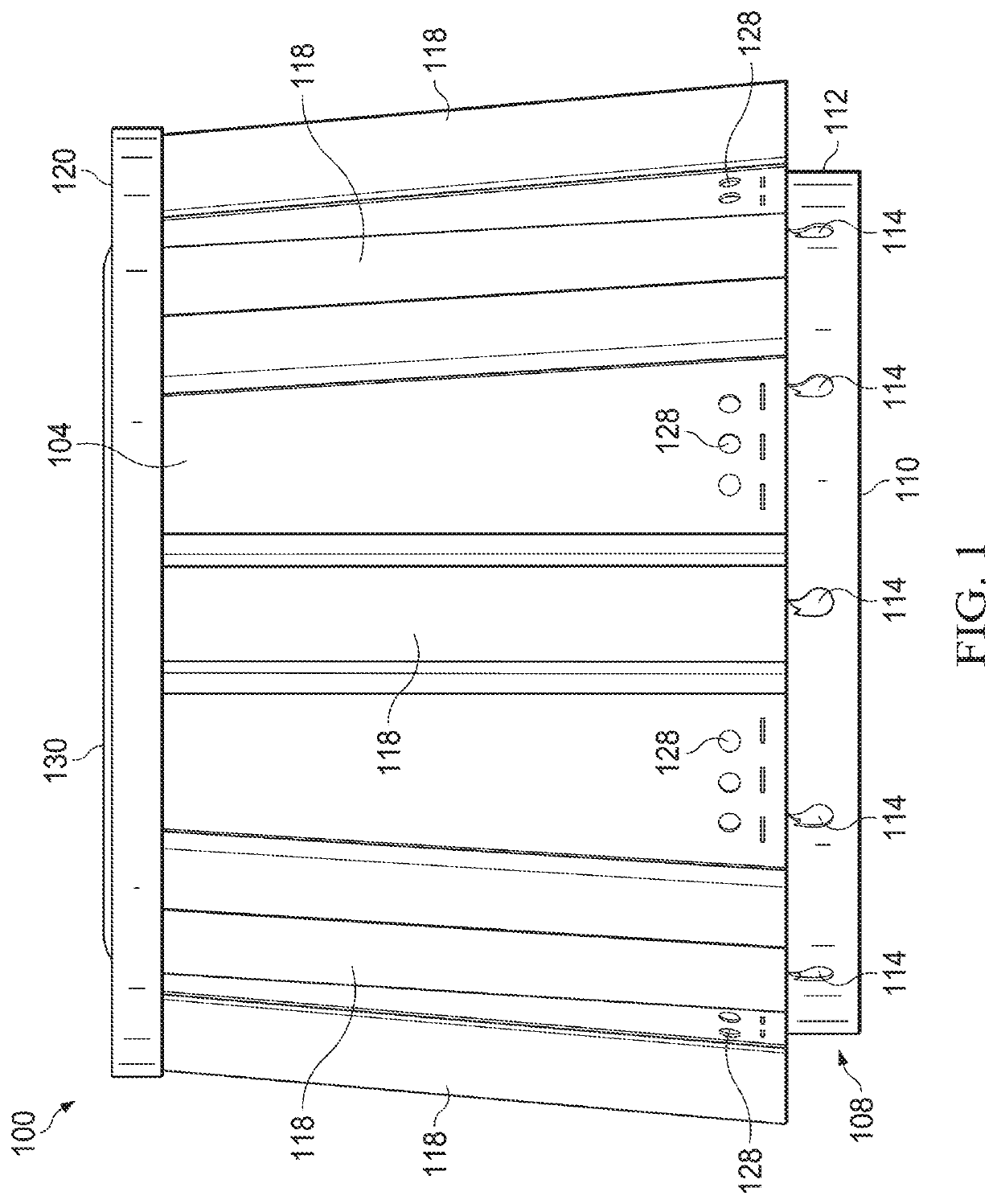
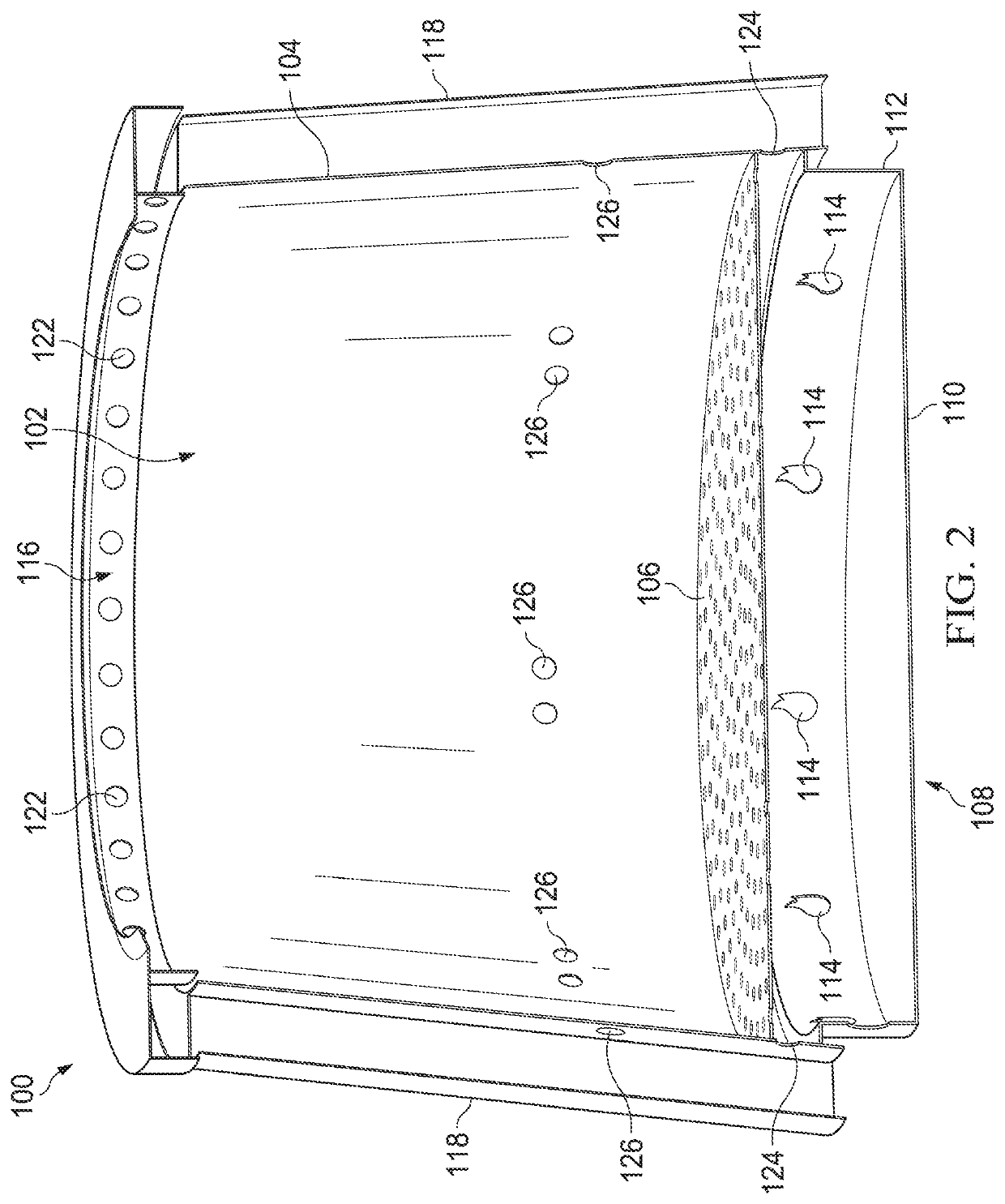
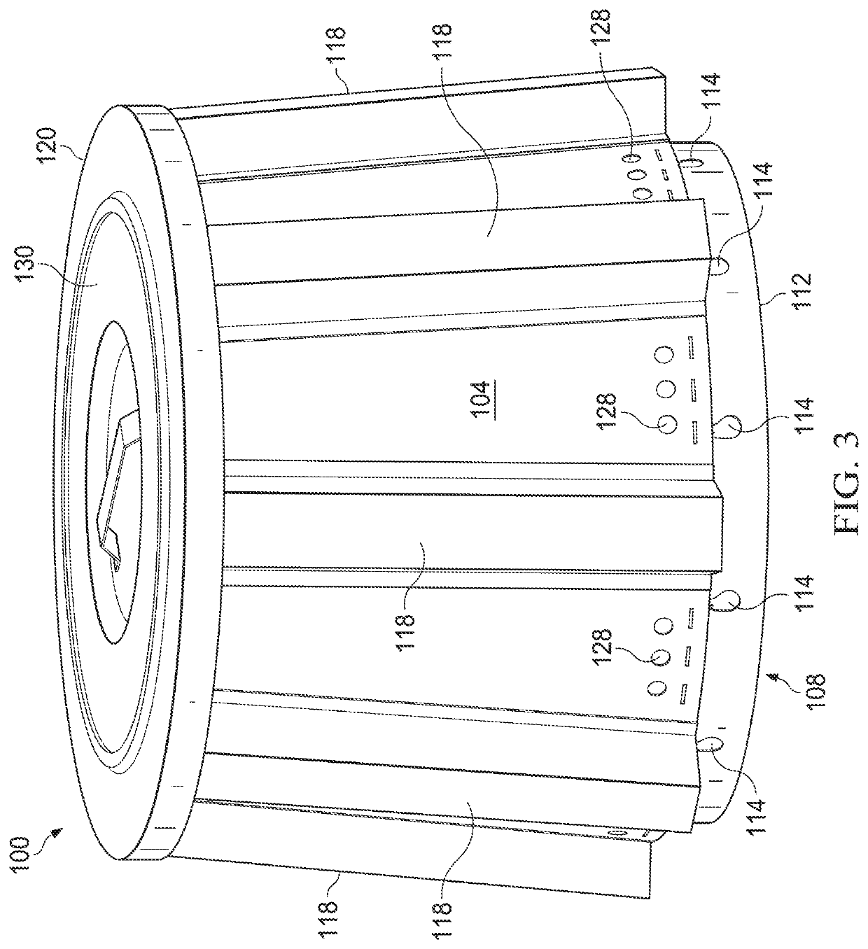
[0036]Referring now to FIGS. 1-4, a fire pit 100 can be seen. FIG. 1 is a side view of the fire pit 100 while FIG. 2 is a side cutaway view, FIG. 3 is a perspective view, and FIG. 4 is a side view with indicated exemplary dimensions of the fire pit of FIG. 1.

[0037]The fire pit 100 may be configured to burn wood pellets, whole sticks of wood, charcoal, or another suitable solid fuel. The fire pit 100 provides an inner chamber 102 bound by an inner chamber wall 104. In various embodiments, the inner chamber 102 is frustoconical in shape and may taper from a relatively wider base to a relatively narrower upper end. Various structures and components of the fire pit 100, including the inner chamber wall 104, may comprise stainless steel or another suitably heat resistant material. The inner chamber wall 104 may be uninsulated and / or of a single layer or thickness. The inner chamber wall 104 is intended to radiate heat from an internal fire outward and away from the fire pit 100 to be enj...


PUM


Abstract

A fire pit includes an engine having at least one wall defining an inner chamber. At least one primary air aperture is defined through the inner chamber wall at a first, lower level, and at least one secondary air aperture is defined through the inner chamber wall at a second, upper level. A fuel grate is supported within the inner chamber at a level between the lower level and the upper level.

Description

CROSS-REFERENCE TO RELATED CASES[0001]This application is a continuation-in-part of U.S. patent application Ser. No. 16 / 578,926 entitled NON-GAS FIRE PIT filed on Sep. 23, 2019 which claims the benefit of U.S. provisional patent application Ser. No. 62 / 734,753 entitled NON-GAS FIRE PIT, filed on Sep. 21, 2018, the contents of which are hereby incorporated by reference.FIELD OF THE INVENTION[0002]This disclosure relates to fire pits in general and, more specifically, to non-gas-burning fire pits.BACKGROUND OF THE INVENTION[0003]Outdoor fire pits have, in the past, been permanent fixtures built from rock, concrete, metals, or other resilient and heavy materials. Often the fire pit is built directly on the ground and is not readily portable. Other fire pits have been developed that may be somewhat portable. However, in an effort to contain fire and ash combustion properties are less than desirable. Smoky fires, possibly with little light or radiated heat, have been the result.[0004]Wha...

Claims


Application Information

Patent Timeline
IPC IPC(8): F23B20/00F23B60/02F23L9/02
CPCF23B20/00F23L9/02F23B60/02F24B3/00F24B5/026F24B13/006F23H2700/006F23C2900/06041F23B2700/018
Inventor HARRINGTON, STEVEN MERRILLSAWALSKI, MICHAELBUTRYM, RYANWOODRUFF, ROBERTKRAMKA, JOELPIUNTI, MEGANCARUTHERS, MONTEL
Owner LAMPLIGHT FARMS
Why Eureka
Try Eureka