
Injection foam molding method

a molding method and injection foam technology, applied in the direction of coatings, etc., can solve the problems of limiting the improvement of productivity and increasing costs, and achieve the effects of promoting the weight reduction of molded objects, and reducing the generation of swirl marks

Active Publication Date: 2021-02-25
TOYOTA JIDOSHA KK
View PDF0 Cites 0 Cited by
  • Summary
  • Abstract
  • Description
  • Claims
  • Application Information

AI Technical Summary

Benefits of technology

The present invention is about a way to make injection foam molded objects that have fewer swirl marks and are less expensive and faster to cycle. This is done by controlling the speed at which the foam material moves through the mold and the amount of gas generated during the process. By setting certain parameters, the method eliminates the need for expensive equipment and tools, reducing costs while also reducing swirl marks and cycle time.

Problems solved by technology

Unfortunately, in the counter pressure method, the internal pressure in the cavity of the mold needs to be increased in advance, and in the heat and cool method, the mold needs to be heated in advance up to the heat deflection temperature of the foamed resin material or higher.
Consequently, special molds and equipment are required, which causes increase in cost.
In addition, the cycle time becomes longer by the time required for pressurizing the cavities and heating the molds, so that there is a limit to improvement in productivity.

Method used


Image

  • Injection foam molding method
  • Injection foam molding method
  • Injection foam molding method

Examples


Embodiment Construction

[0029]Hereinafter, embodiments of the present disclosure will be described with reference to the drawings. In the present embodiment, description will be provided on the case in which the present disclosure is applied as an injection foam molding method of molding an interior component (for example, a door trim, an instrument panel, etc.) of an automobile, which is molded as an injection foam molded article.

[0030]Schematic Configuration of Injection Foam Molding Apparatus

[0031]Before the injection foam molding method will be described, a schematic configuration of an injection foam molding apparatus in which the injection foam molding method is performed will be described.

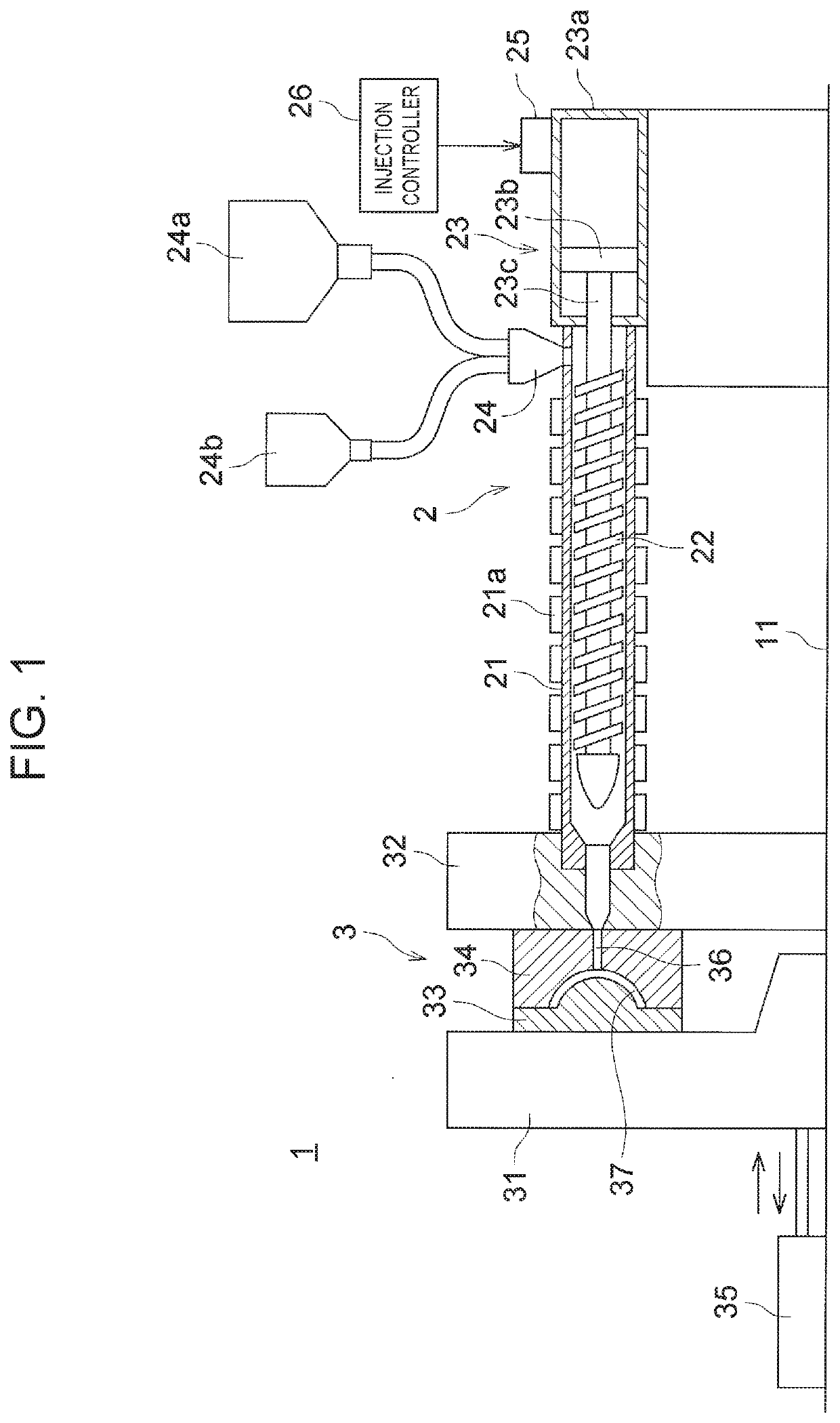
[0032]FIG. 1 is a view showing a schematic configuration of an injection foam molding apparatus 1 according to the present embodiment. As shown in FIG. 1, the injection foam molding apparatus 1 includes: an injection unit 2 that injects a foamed resin material; and a mold unit 3 that is supplied with the foamed res...


PUM

PropertyMeasurementUnit
Massaaaaaaaaaa
Water holding capacityaaaaaaaaaa
Pressureaaaaaaaaaa

Abstract

In an injection foam molding method, a relationship between a flow front moving speed (cm / s) of a foamed resin material in an injection step of injecting the foamed resin material into a cavity and amount of gas generated per 1 g of a resin material (ml / g) is defined as follows: the amount of gas generated per 1 g of the resin material is 0.36 ml / g or more; and the flow front moving speed (cm / s) is 75×the amount of gas generated per 1 g of the resin material (ml / g)−35 or more and 12 cm / s or more.

Description

CROSS-REFERENCE TO RELATED APPLICATIONS[0001]This application claims priority to Japanese Patent Application No. 2019-150828 filed on Aug. 21, 2019, which is incorporated herein by reference in its entirety including the specification, drawings and abstract.BACKGROUND1. Technical Field[0002]The present disclosure relates to an injection foam molding method. In particular, the present disclosure relates to improvement of an injection foam molding method capable of reducing generation of swirl marks.2. Description of Related Art[0003]Conventionally, an injection foam molded article has been used as a resin molded article such as a door trim in an automobile, for example. In the injection foam molding method for obtaining such an injection foam molded article, air bubbles are generated inside a foamed resin material at the time of injection molding so as to reduce generation of warps or sink marks in the injection foam molded article. As the injection foam molding method, a counter pre...

Claims


Application Information

Patent Timeline
IPC IPC(8): B29C44/38B29C45/00
CPCB29C44/38B29K2105/04B29C45/0025B29C45/0046B29C44/02B29C44/422B29C44/424B29C44/60B29C44/3415B29C44/3442B29C44/42B29C44/3446B29C45/77B29C2045/0039B29K2023/12B29K2105/0005
Inventor KAMEYAMA, TSUYOSHISUGIMURA, KIKUOFUKUTA, TAROKANDORI, HIROKAZU
Owner TOYOTA JIDOSHA KK
Learn More