[0054]In the drawings, the same or similar elements and/or parts are provided with the same reference numbers in order to prevent the item from needing to be reintroduced.
DETAILED DESCRIPTION
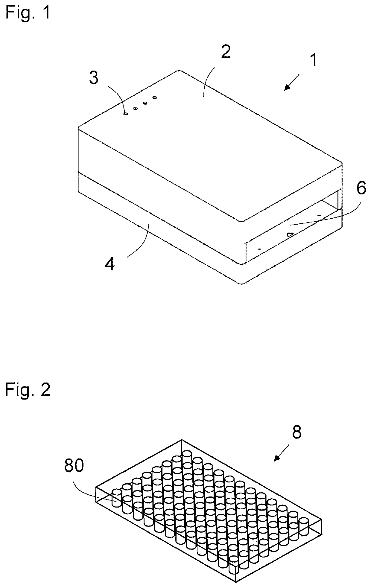
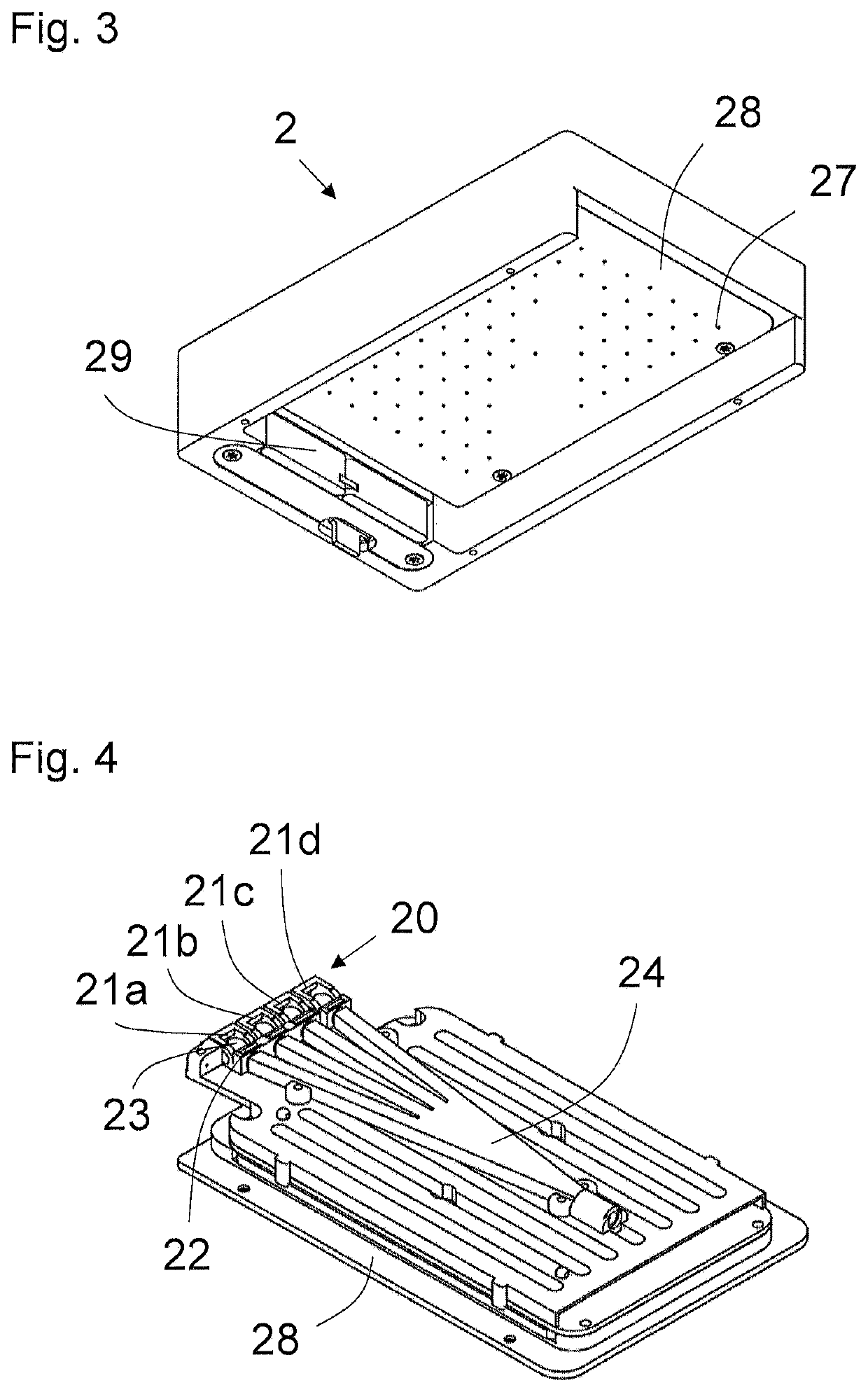
[0055]FIG. 1 schematically shows an exemplary embodiment of a transmission device 1. The transmission device 1 comprises an illumination device 2 and a detection device 4, between which there is an intermediate space 6 formed as a rectangular opening. The intermediate space 6 can be configured such that a microtiter plate 8 of the like shown in FIG. 2 can be inserted so as to fit exactly therein. The dimensions of the intermediate space 6 therefore substantially correspond to the dimensions of the microtiter plate 8, as a result of which the transmission device 1 has a compact design. Furthermore, the transmission device 1 comprises a plurality of status lights 3. Said status lights 3 are in each case assigned to one light-emitting diode arranged in the illumination device 2. The light-emitting diodes are hidden in FIG. 1. When one of the light-emitting diodes emits light, the assigned status light 3 also lights up. For reasons of clarity, only one of the status lights 3 has been provided with a reference sign.
[0056]The microtiter plate 8 shown by way of example in FIG. 2 is of a format having ninety-six cavities 80, and once again only one of these cavities 80 has been provided with a reference sign. The samples to be examined are arranged in these cavities 80 before the microtiter plate 8 is inserted into the intermediate space 6. Since the dimensions of microtiter plates 8 meet an ANSI standard, the intermediate space 6 can be configured to be complementary in shape to these dimensions.
[0057]FIG. 3 is a diagram of the illumination device 2, whereby a view obliquely from below has been selected for FIG. 3. The illumination device 2 comprises an ejection device 29, by means of which the microtiter plate 8 can be quickly and simply ejected from the intermediate space 6. A holding plate 28 comprising a number of emission openings 27, of which only one has been provided with a reference sign, is arranged directly above the inserted microtiter plate 8. The number of emission openings 27 corresponds to the number of cavities 80 in the microtiter plate 8. Therefore, in the example shown in FIG. 3, there are ninety-six emission openings 27. The emission openings 27 are arranged such that, when the microtiter plate 8 is inserted, each emission opening 27 is arranged centrally over a cavity 80.
[0058]The internal structure of the illumination device 2 is shown in FIGS. 4 and 5. The view selected for FIGS. 4 and 5 corresponds to the view in FIG. 1, and therefore the bottom of the holding plate 28 hidden in FIGS. 4 and 5 corresponds to the bottom of the holding plate 28 shown in FIG. 3. The illumination device 2 comprises an emission source 20, which comprises four light-emitting diodes 21a, 21b, 21c, 21d in the example shown in FIG. 4. By way of example, the emission light of the light-emitting diode 21a has a wavelength of 405 nm, the emission light of the light-emitting diode 21b has a wavelength of 450 nm, the emission light of the light-emitting diode 21c has a wavelength of 540 nm and the emission light of the light-emitting diode 21d has a wavelength of 630 nm. By providing a plurality of light-emitting diodes with different wavelengths, various examinations can be performed using the same transmission device 1. A spherical lens 23 that parallelizes the exiting emission light is in each case arranged directly behind the light-emitting diodes 21a to 21d. For reasons of clarity, again only one of the spherical lenses 23 has been provided with a reference sign. An interference filter 22 that restricts the wavelength spectrum of the emission light from the light-emitting diodes 21a to 21d is arranged behind each spherical lens 23. According to another embodiment not shown in FIG. 4, an additional spherical lens that focuses the emission light is arranged behind each interference filter 22.
[0059]A light mixer 24 is arranged behind the interference filters 22 or the additional spherical lenses. Said light mixer 24 homogenizes the incident emission light such that it is distributed with equal intensity in the cross-section of the light mixer 24. For this purpose, according to the embodiment shown in FIG. 4, the light mixer 24 has a rectangular cross-section. If only one individual light-emitting diode 21a is provided, the light mixer 24 for example has the shape of a rod with a rectangular cross-section. However, if a plurality of light-emitting diodes 21a to 21d are provided, as shown in FIG. 4, the light mixer 24 gathers the emission light from the light-emitting diodes 21a to 21d. As shown in FIG. 4, this may for example be done by means of four converging arms. Alternatively, the light mixer 24 may have a substantially triangular base surface, which, when compared with the embodiment shown in FIG. 4, occupies the area between the arms.
[0060]FIG. 5 shows the diagram from FIG. 4 enlarged. Partial beam paths 25 are also schematically shown, onto which the emission light of the light-emitting diodes 21a to 21d exiting the optical waveguide 24 is split. For this purpose, a bundle of optical waveguides 26 into which an equal portion of the emission light is coupled in each case is arranged at the exit of the light mixer 24. Said optical waveguides 26 each lead from the exit of the light mixer 24 to an emission opening 27 in which a spherical lens (not shown) for focusing the emission light is arranged in each case. The partial beam paths 25 that extend in the optical waveguides 26 to the emission openings 27 are transmission beam paths. An additional optical waveguide 26, as a reference beam path 30, leads back to a reference detector unit 32, which is arranged next to the light-emitting diodes 21a to 21d. By means of this reference detector unit 32, aging of the light-emitting diodes 21a to 21d and/or a change in the intensity of the emission light can be determined.
[0061]FIG. 6 schematically shows a detection device 4 that is arranged below the illumination device 2 and the inserted microtiter plate 8. In a region of the surface of the detection device 4 that substantially corresponds to the surface area of the inserted microtiter plate 8, the detection device 4 comprises an angle-dependent filter 42 that is configured as a film in the diagram in FIG. 6. Said angle-dependent filter 42 is configured to substantially only let through light beams of which the angle of incidence is smaller than a predetermined critical angle. The critical angle is related to the transmission beam paths of the emission light in the intermediate space 6, which corresponds to a vertical line on the angle-dependent filter 42. In this way, scattered light, which is incident in the intermediate space 6 at an oblique angle, is prevented from passing through the angle-dependent filter 42, and therefore only the light signals from the samples in the intermediate space 6 can pass through.
[0062]FIG. 7 shows an exploded diagram of the detection device 4 from FIG. 6. FIG. 7 shows that a detector plate 49 is arranged below the angle-dependent filter 42, which detector plate comprises a series of detector openings 41 arranged centrally below the emission openings 27 and cavities 80 in each case. A detector unit having at least one detector 40 is arranged in each of these detector openings 41. Said detector units are hidden from the perspective in FIG. 7. The detectors 40 are for example photodiodes that are sensitive to different wavelength ranges. Spherical lenses 43 are in each case arranged in the openings in order to focus the emission light or the light signals onto the detectors 40.
[0063]Taking FIGS. 3, 5 and 7 together, it is clear that each of the transmission beam paths extends from the light mixer 24 through an optical waveguide 26, an emission opening 27, the intermediate space 6 or a cavity 80, and the angle-dependent filter 42 to a detector 40 or detector unit. After exiting the emission openings 27, the transmission beam paths extend in parallel with one another.
[0064]FIGS. 8a to 8c show various alternative measurement cycles 56, which are run through during examination of the samples. Said measurement cycles 56 each comprise a number of light measurements 51a, 51b, 51c, 51d and a number of dark measurements 54. During a light measurement 51a, 51b, 51c, 51d, in each case one of the light-emitting diodes 21a, 21b, 21c, 21d lights up for a first period of time, for example 5 ms. During a dark measurement, none of the light-emitting diodes 21a to 21d lights up for a second period of time, for example 5 ms as well. The microtiter plate 8 is arranged in the intermediate space 6 during the entire measurement cycle 56. During examination of the samples, the measurement cycles 56 are each repeated several times in order to obtain measurements with a high signal strength and also in order to be able to filter out high-frequency interference.
[0065]In the measurement cycle shown in FIG. 8a, a dark measurement 54 is measured after each light measurement 51a to 51d, the different light-emitting diodes 21a to 21d supplying the emission light sequentially during the light measurements. Alternatively, the measurement cycle 56 shown in FIG. 8b comprises the four light measurements 51a to 51d and only one dark measurement 54, which is subtracted from all light measurements 51a to 51d. The measurement cycle 56 shown in FIG. 8c comprises only one light measurement 51a and one dark measurement 54. This measurement cycle is useful, for example, if the samples only have to be investigated with one wavelength or if the examination is to be carried out with other wavelengths after the examination has finished after several repetitions of the measurement cycle 56 with the first wavelength.
[0066]In all measurement cycles 56 shown in FIGS. 8a to 8c, the dark measurement 54 is subtracted from the light measurements 51a to 51d measured by the same detector unit, and therefore a background intensity is determined for each detector unit separately.
[0067]While there has been shown and described what is considered to be preferred embodiments, it will, of course, be understood that various modifications and changes in form or detail could readily be made without departing from the spirit of the invention. It is therefore intended that the invention be not limited to the exact forms described and illustrated, but should be constructed to cover all modifications that may fall within the scope of the appended claims.
LIST OF REFERENCE SIGNS
[0068]1 Transmission device
[0069]2 Illumination device
[0070]3 Status light
[0071]4 Detection device
[0072]6 Intermediate space
[0073]8 Microtiter plate
[0074]20 Emission source
[0075]21a, 21b, 21c, 21d Light-emitting diode
[0076]22 Interference filter
[0077]23 Spherical lens
[0078]24 Light mixer
[0079]25 Partial beam paths
[0080]26 Optical waveguide
[0081]27 Emission opening
[0082]28 Holding plate
[0083]29 Ejection device
[0084]30 Reference beam path
[0085]32 Reference detector
[0086]40 Detector
[0087]41 Detector opening
[0088]42 Angle-dependent filter
[0089]43 Spherical lens
[0090]49 Detector plate
[0091]51a, 51b, 51c, 51d Light measurement
[0092]54 Dark measurement