Human condition detecting device

a technology for detecting devices and human conditions, applied in the field of non-contact detection, can solve problems such as difficulty in detecting the condition of people in dim or dark rooms, and achieve the effect of avoiding any risk of invading the privacy of peopl

Pending Publication Date: 2021-03-04
GIGA BYTE TECH CO LTD
View PDF4 Cites 2 Cited by
  • Summary
  • Abstract
  • Description
  • Claims
  • Application Information

AI Technical Summary

Benefits of technology

[0004]It is the primary objective of the present invention to provide a human condition...

Problems solved by technology

However, such use of the cameras could invade the privacy of patients or cared-for people and it would be difficult to detect...

Method used


Image

  • Human condition detecting device
  • Human condition detecting device
  • Human condition detecting device

Examples


Embodiment Construction

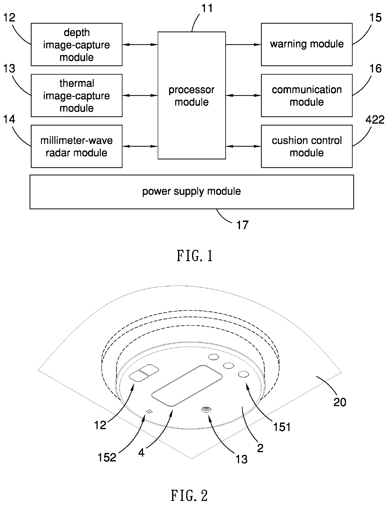
[0026]Referring to FIG. 1, a human condition detecting device comprises a processor module 11, a depth image-capture module 12, a thermal image-capture module 13, a millimeter-wave radar module 14, a warning module 15, a power supply module 17. The processor module 11 is electrically connected to all the modules 12-15 and 17. The depth image-capture module 12 and the thermal image-capture module 13 are utilized to capture images of a target area. The millimeter-wave radar module 14 is utilized to detect breath and heartbeat in the target area to generate a detecting signal. The warning module 15 is utilized to generate a warning. The power supply module 17 is electrically connected to the modules 11-15 to provide power. In the first embodiment, the human condition detecting device could further comprise a communication module 16 and a cushion control module 422 that are electrically connected to the processor module 11.

[0027]The target area can be an area where a hospital bed is loc...


PUM


Abstract

A human condition detection device comprises a depth image-taking module for taking a depth image of a target area. A millimeter-wave radar module detects breaths or heartbeats in the target area to provide a signal. A thermal image-taking module takes a thermal image of the target area. A processor module determines whether a person is in the target area based on the depth image. The processor module determines whether there is any breath or heartbeat based on the signal if a person is in the target area. The processor module determines whether there is any abnormal vital sign of the person in the target area based on the signal and the thermal image if there is a breath or heartbeat in the target area. The processor module actuates the warning module to provide a warning if there is an abnormal vital sign of the person in the target area.

Description

BACKGROUND OF INVENTION1. Field of Invention[0001]The present invention relates to non-contact detection of a posture, a movement, breath, heartbeat and temperature of a person and, more particularly, to a device for detecting conditions of a person in a hospital or a nursing home.2. Related Prior Art[0002]The demands for health care and nursing have recently increased. Accordingly, the demands for labor in those industries have increased as well. To solve the manpower shortages, cameras are now utilized to monitor and analyze human conditions to facilitate health care and / or nursing of babies, children, elderly, or patients. However, such use of the cameras could invade the privacy of patients or cared-for people and it would be difficult to detect the condition of them in a dim or dark room since the analysis of the images captured by the cameras is based on the visible light.[0003]The present invention is therefore intended to obviate or at least alleviate the problems encountere...

Claims


Application Information

Patent Timeline
IPC IPC(8): A61B5/0205G08B21/04H04N7/18G06K9/00H04N5/225A61B5/01A61B5/05A61B5/00A61B5/11G01S13/62
CPCA61B5/02055G08B21/04H04N7/18G06K9/00362G06K9/00335A61B5/02444A61B5/015A61B5/05A61B5/746A61B5/1128G01S13/62H04N5/2252A61B5/0077A61B5/01A61B5/1116A61B5/0507A61B5/7282A61B5/0816H04N5/2226G01S7/415G08B21/0469G06V40/10G06V40/15G06V40/20H04N23/51
Inventor PAI, KUANG-HUACHANG, CHIH-LIANGLU, JYUN-HONGYEH, MIM-NANCHEN, HUNG-TA
Owner GIGA BYTE TECH CO LTD
Why Eureka
Try Eureka