Vehicle control device, vehicle control method, and recording medium storing vehicle control program
a vehicle control and control method technology, applied in the field of vehicle control devices, vehicle control methods, and recording media storing vehicle control programs, can solve the problem of delayed activation of software needed for vehicle control
- Summary
- Abstract
- Description
- Claims
- Application Information
AI Technical Summary
Benefits of technology
Problems solved by technology
Method used
Image
Examples
first embodiment
Summary of First Embodiment
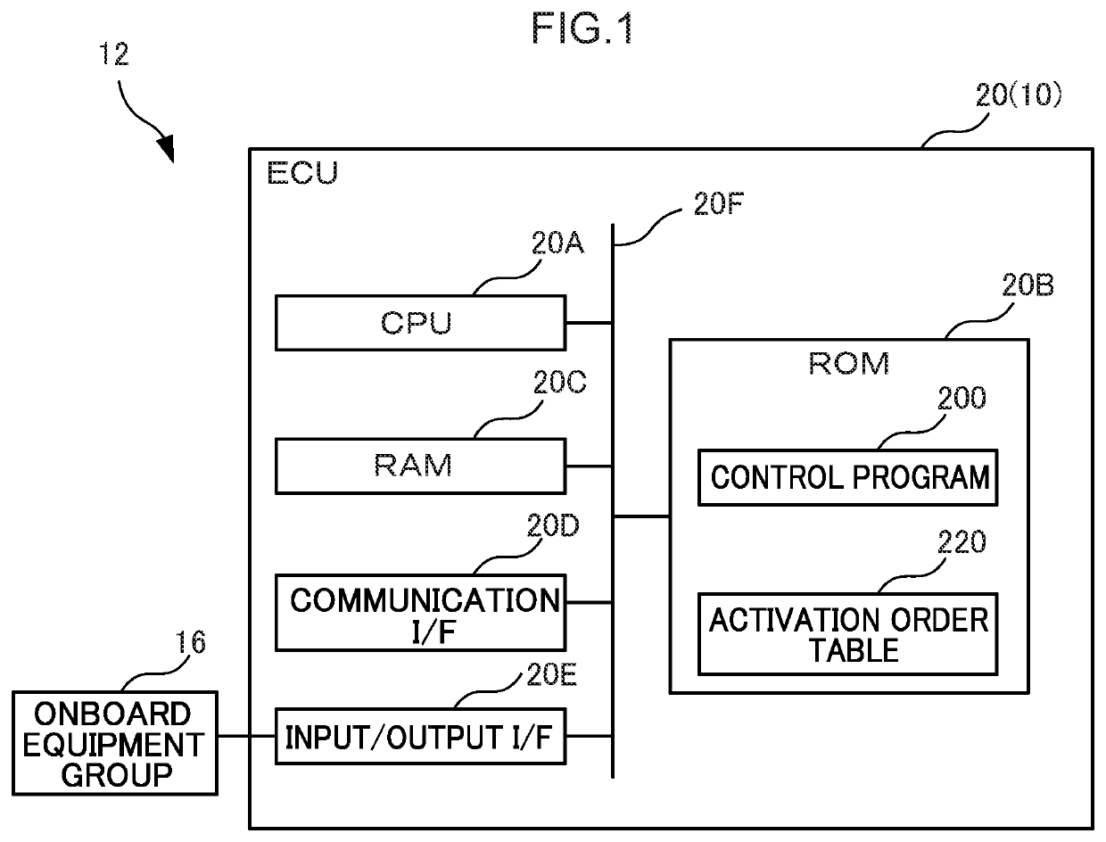
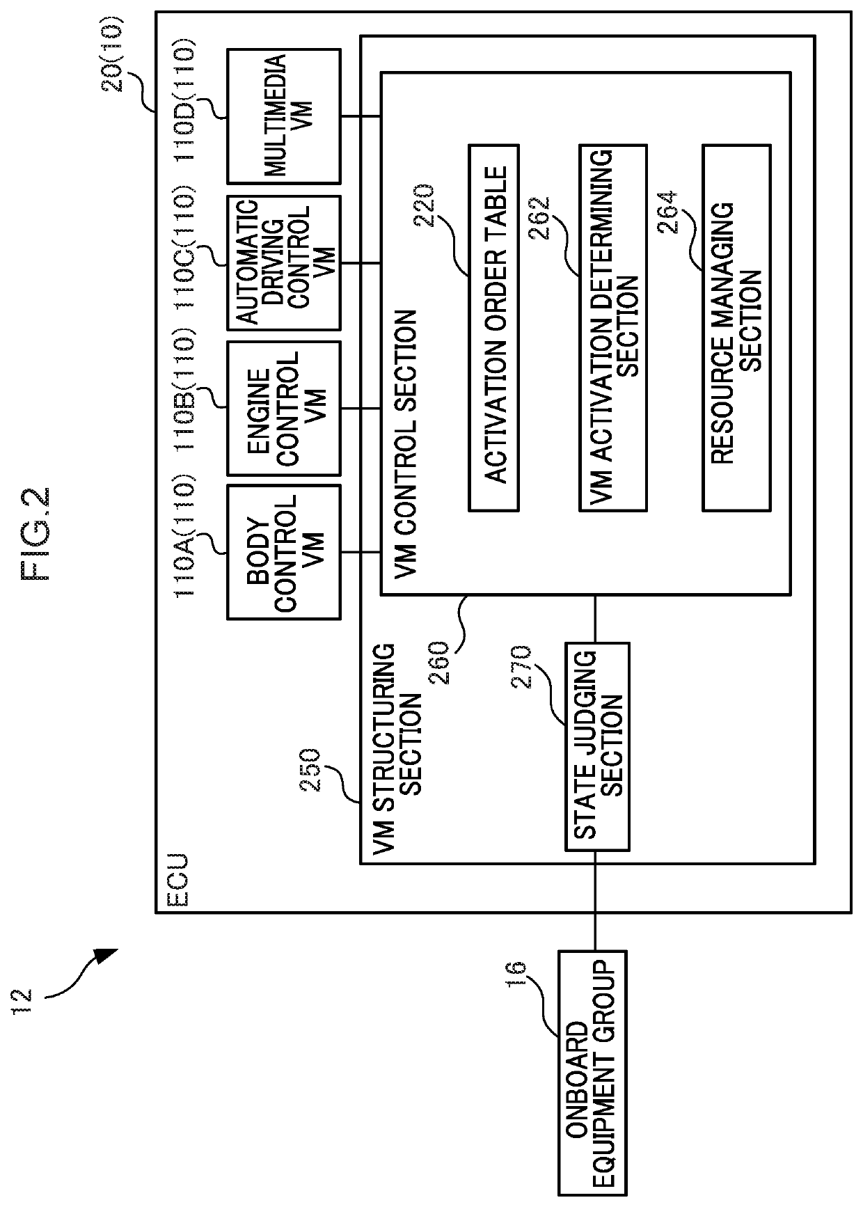
[0074]The plural VMs 110 that are virtualized by the VM structuring section 250 are structured in the control device 10 of the present embodiment. Equipment (the onboard equipment group 16) that are installed in the vehicle 12 are controlled by the respective VMs 110. In this control device 10, the VM control section 260 switches the order of carrying out activation or stoppage of the plural VMs 110, in accordance with the state of the vehicle 12 that is judged by the state judging section 270.
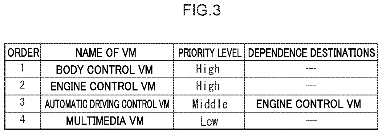
[0075]For example, in a case in which the vehicle 12 is in state B, and the respective VMs 110 that are currently stopped are to be activated respectively, at the control device 10, activation is carried out in accordance with the order that is prescribed in the activation order table 220 (refer to step S120 through step S136 of FIG. 6). On the other hand, if the vehicle 12 is in state A, and some of the VMs 110 are to be ended, at the control device 10, the activati...
second embodiment
[0082]In the first embodiment, the VM control section 260 is provided at the VM structuring section 250 that functions as a hypervisor. In contrast, the second embodiment differs from the first embodiment with regard to the point that the VM control section 260 is structured at one of the VMs 110. The point that differs from the first embodiment is described hereinafter. Note that the same structures are denoted by the same reference numerals, and description thereof is omitted.
[0083]As shown in FIG. 7, in the ECU 20 of the present embodiment, the VMs 110 include a VM 120 for control, in addition to the body control VM 110A, the engine control VM 110B, the automatic driving control VM 110C and the multimedia VM 110D. In the present embodiment, the VM 120 for control has the VM control section 260. The VM structuring section 250 treats the VM 120 for control as a special VM 110, and handles it as a structure that is different from the other VMs 110, and activates the VM 120 for contr...
third embodiment
[0086]The third embodiment differs from the first embodiment with regard to the point that the state judging section 270 is provided at another ECU 20. The point that differs from the first embodiment is described hereinafter. Note that the same structures are denoted by the same reference numerals, and description thereof is omitted.
[0087]As shown in FIG. 8, the control device 10 of the present embodiment includes a main ECU 22 and a sub ECU 23 as the ECUs 20. In the present embodiment, the respective VMs 110, the VM structuring section 250 and the VM control section 260 are provided at the main ECU 22, and the state judging section 270 is provided at the sub ECU 23. The VM control section 260 is notified of the state of the vehicle 12, which is judged at the state judging section 270, by communication between the ECUs 20 (e.g., CAN).
[0088]Operation and effects that are similar to those of the first embodiment can be obtained in the present embodiment as well.
PUM
 Abstract
Description
Claims
Application Information
 - R&D
- Intellectual Property
- Life Sciences
- Materials
- Tech Scout
- Unparalleled Data Quality
- Higher Quality Content
- 60% Fewer Hallucinations
Browse by: Latest US Patents, China's latest patents, Technical Efficacy Thesaurus, Application Domain, Technology Topic, Popular Technical Reports.
© 2025 PatSnap. All rights reserved.Legal|Privacy policy|Modern Slavery Act Transparency Statement|Sitemap|About US| Contact US: help@patsnap.com


