
Digital control device

a digital control device and control system technology, applied in pump control, pump control, positive displacement liquid engine, etc., can solve the problems of delay in activation and take too long

Active Publication Date: 2013-03-26
MULTIQUIP
View PDF15 Cites 3 Cited by
  • Summary
  • Abstract
  • Description
  • Claims
  • Application Information

AI Technical Summary

Benefits of technology

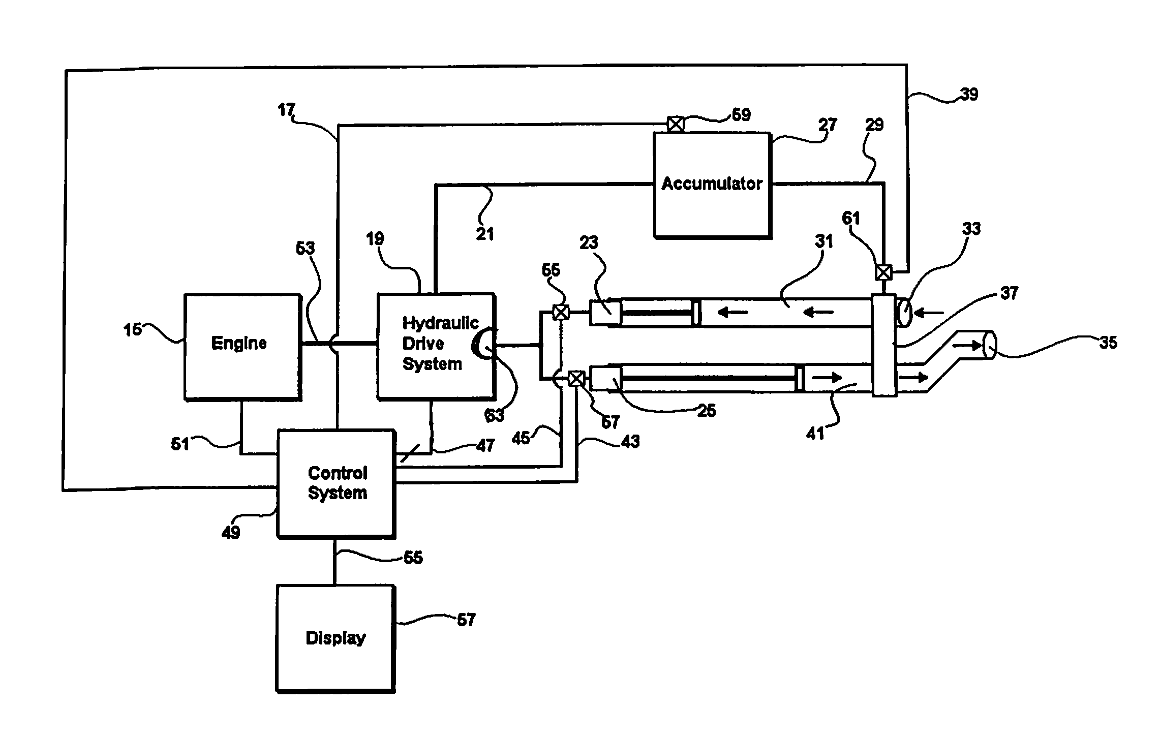
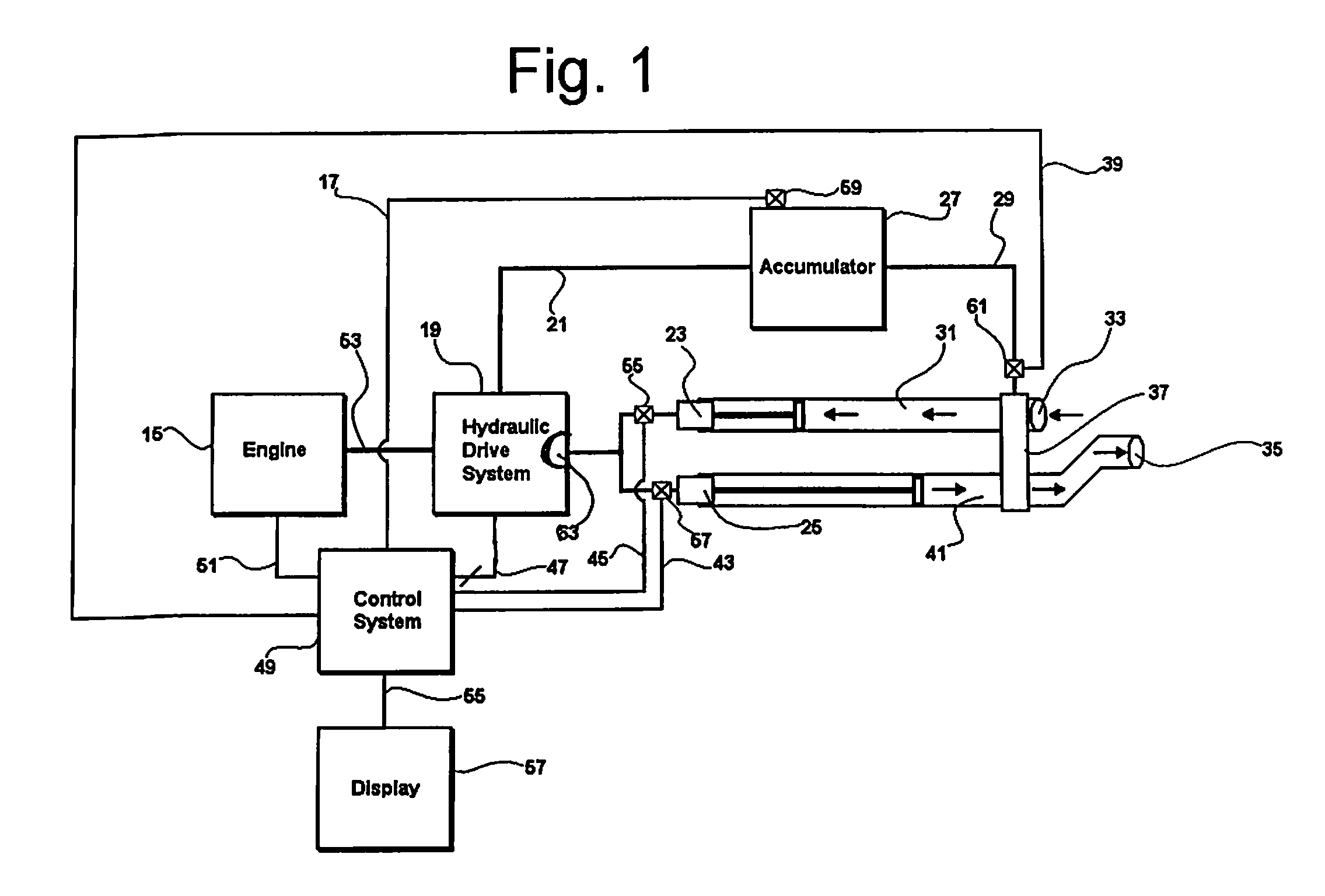
[0010]The system also reduces load on the engine driving the pump during startup. This minimizes the load on the engine starter and battery and therefore increases its operational lifetime. The system also delays the activation of the concrete placement pump when the engine is at idle allowing the engine to reach full RPM and maximum horsepower before the full load is applied the engine. This prevents engine lugging and sometimes engine stalling, thus increasing the engines operational life.

Problems solved by technology

This may take too long as the concrete could set in the pump or tube and become hard.
The system also delays the activation of the concrete placement pump when the engine is at idle allowing the engine to reach full RPM and maximum horsepower before the full load is applied the engine.

Method used


Image

  • Digital control device
  • Digital control device
  • Digital control device

Examples


Embodiment Construction

[0016]While the invention is susceptible of various modifications and alternative constructions, certain illustrated embodiments thereof have been shown in the drawings and will be described below in detail. It should be understood, however, that there is no intention to limit the invention to the specific form disclosed, but, on the contrary, the invention is to cover all modifications, alternative constructions, and equivalents falling within the spirit and scope of the invention as defined in the claims.

[0017]To deliver concrete to a job site impassable by delivery trucks, concrete placement pumps are utilized. These pumps move concrete through a tube to the region to receive the concrete. To facilitate this pumping, hydraulically driven piston pumps flow oil through hydraulic valves which are controlled by electric solenoids. These hydraulically driven piston pumps exhibit many different failure modes in their lifetime. Of these failure modes, the most common is either a clog in...


PUM


Abstract

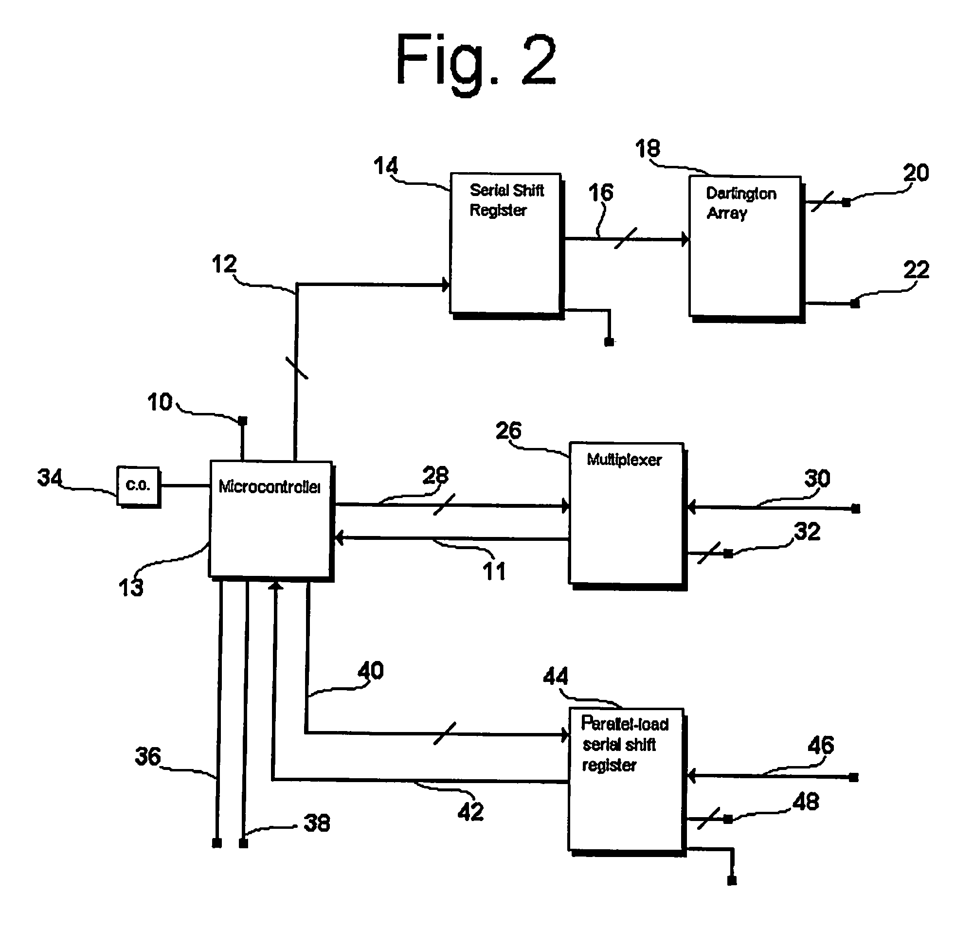
A digital control system for monitoring and controlling a concrete pumping system. A microcontroller provides control signals and receives feedback from associated comparator switch subsystems. Feedback from the comparator switch subsystems is used by a microcontroller to determine whether short circuit or open circuit malfunctions are occurring on solenoids valves attached to the output of the comparator switch subsystems. Said control system exhibits an electronic control means to control the admittance or interruption of current through said solenoids. Individual solenoid status is sent to a graphical display where an operator views said display to diagnose failure modes. The microcontroller further monitors the establishment of temporal initial conditions and limits operational pump activity until said temporal conditions are met.

Description

FIELD OF THE INVENTION[0001]The invention generally relates to an automated monitoring control system for a hydraulic driven pump, and more particularly to a hydraulic driven concrete pump used to pump concrete at a job site. The system monitors current flow to various solenoids and valves in the hydraulic drive to provide immediate diagnostic information, and sends control signals to the solenoids and valves based upon the monitored condition.BACKGROUND OF THE INVENTION[0002]In the concrete delivery industry, delivery of concrete to the job site often requires the delivery vehicle to be at a much different lateral distance and / or elevation than a particular region of the site that is to receive concrete. To overcome this obstacle concrete placement pumps are often employed to move the concrete over the distance required.[0003]Within these concrete placement pumps, the concrete is pumped through a long tube affixed to the outlet of concrete placement pump moved to the delivery area ...

Claims


Application Information

Patent Timeline
Patent Type & Authority Patents(United States)
IPC IPC(8): F04B49/00
CPCF04B9/117F04B15/02
Inventor SANGER, JOEHUDSON, FORRESTFALER, WARREN
Owner MULTIQUIP
Learn More