Roughness tester

Active Publication Date: 2021-03-11
MITUTOYO CORP
View PDF0 Cites 0 Cited by
  • Summary
  • Abstract
  • Description
  • Claims
  • Application Information

AI Technical Summary

Benefits of technology

The purpose of this invention is to create a roughness tester that is more efficient and accurate in measuring roughness.

Problems solved by technology

However, holding the compact roughness tester with one hand and pressing the measurement start button with the other hand is rather troublesome.
This is one of the reasons for preventing improvement of measurement efficiency.
However, the stylus itself is very small and is difficult to visually recognize, and this easily causes measurement errors depending on the skill of the operator.

Method used


Image

  • Roughness tester
  • Roughness tester
  • Roughness tester

Examples


first exemplary embodiment

[0026]A roughness tester according to a first exemplary embodiment of the present invention is described below.

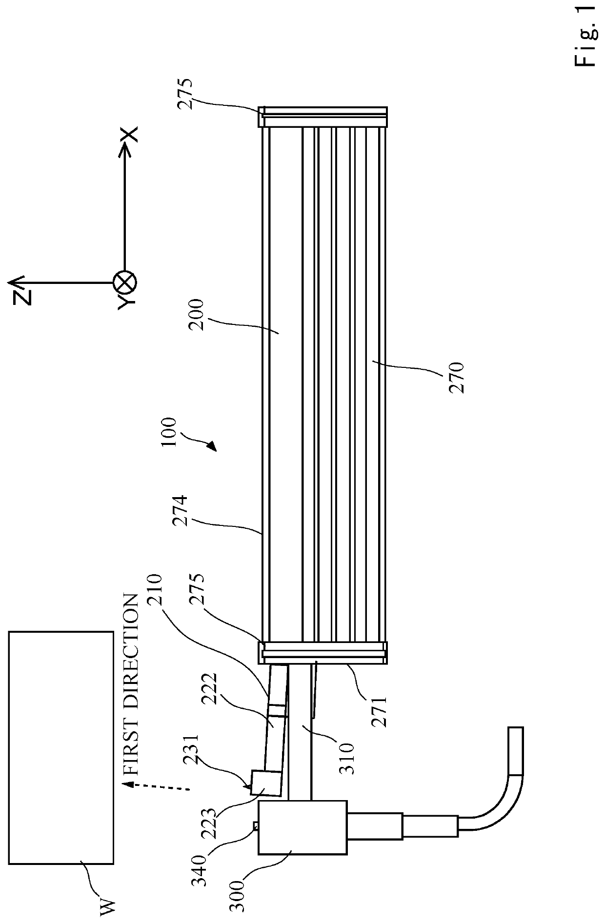
[0027]FIG. 1 is a side view of a roughness tester.

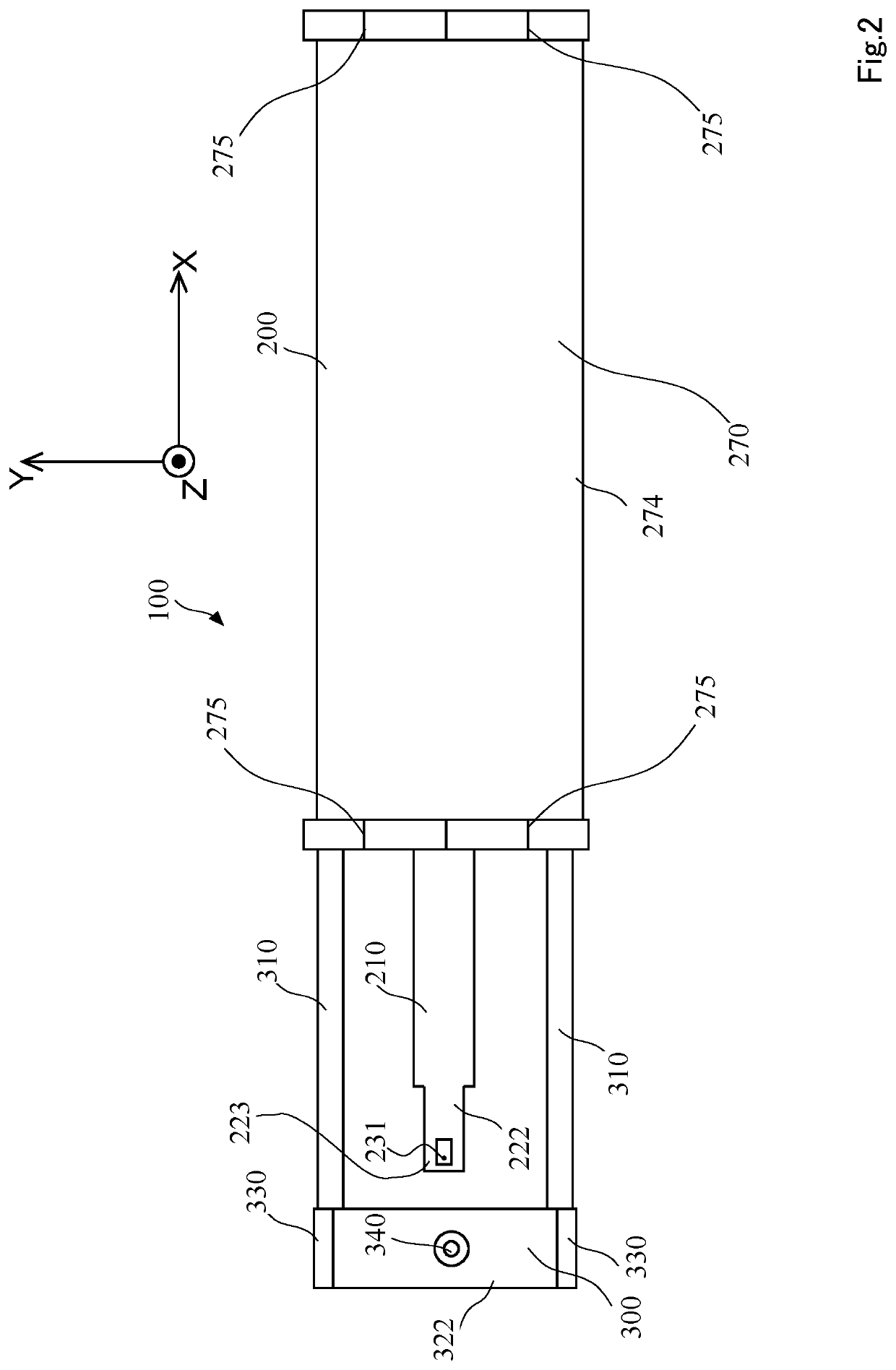
[0028]FIG. 2 is a view of the roughness tester when viewed from the positive side of a Z axis.

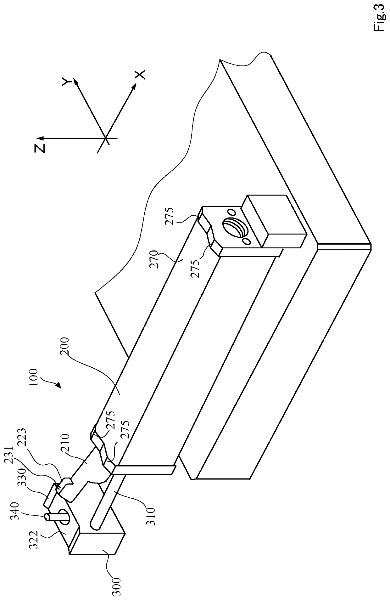
[0029]FIG. 3 is a perspective view of the roughness tester.

[0030]FIG. 4 is a cross sectional view of the roughness tester.

[0031]A roughness tester 100 according to the present exemplary embodiment includes a measurement main body 200, a height detector 300, and a control unit 400. (The control unit 400 is shown in FIGS. 4 and 6.)

[0032]The configuration of the measurement main body 200 is basically common to the configuration of a known roughness tester. The configuration of the measurement main body 200 is briefly described below. The measurement main body 200 includes, for example, a stylus unit 210, a drive unit 250, and a main-body housing part 270 as shown in FIG. 4.

[0033]The stylus unit 210 includes a casing body 220 having a s...

usage example 1

[0068]FIG. 9 is a diagram showing a suitable usage example of the roughness tester 100.

[0069]In FIG. 9, a transportation table 610 having a flat top face is prepared.

[0070]The transportation table 610 includes grips 620 as gripping means on both ends thereof. On the top face of the transportation table 610, a plurality of (here, three) roughness testers 100 is installed. The roughness testers 100 are installed in a manner such that the main-body base faces 274 face upward. In this manner, a plurality of roughness testers 100 is unitized. The unitized roughness tester 100 is referred to as a roughness tester unit 600. To perform roughness measurement, the operator successively places workpieces W on which the roughness measurement is performed in such a manner as to straddle the height detector 300 and the front main-body support foot 275. The operator is only required to successively place the workpieces W and is not required to perform operation, such as pushing a start button.

[007...

first modification

[0072]The height detector detects the height of the workpiece surface in the first exemplary embodiment, but a height detector 300A may be provided, as exemplified in FIG. 11, to detect the height position (posture) of the stylus unit 210. In FIG. 11, the height detector 300A is provided to detect that the posture of the stylus unit 210 is parallel with the drive axis. Here, the height detector 300A is held by a coupling rod 310A extending from the front end face 271 of the main-body housing part 270. However, the height detector 300A may be provided inside the main-body housing part 270. A supporting base part 500 may be provided in such a manner as to face the front end face 271 of the main-body housing part 270, interposing the stylus unit 210 (the skid 223) therebetween to provide a support foot 510, but the supporting base part 500 may be omitted. In the height-reference-value setting unit 411 of the control unit 400, a detect value of the height detector 300A when the stylus 2...


PUM


Abstract

There is provided a roughness tester that improves measurement efficiency and roughness measurement accuracy.A roughness tester includes a stylus unit including a stylus that is provided in such a manner as to protrude from and retract into a through hole of a skid and performs scanning movement along a surface of a workpiece, and a stylus displacement detecting unit that detects displacement of the stylus, and a drive unit that moves the stylus unit forward and backward in a drive-axis direction. The roughness tester further includes a height detector that is provided in such a manner as to face a front end face of the main-body housing part, interposing the skid between the height detector and the front end face and that detects a height of an object in a direction parallel with a measurement axis. When the height detector detects the object at the same height of the height of the main-body support foot in the measurement axis direction, the drive unit automatically starts driving in order for the stylus unit to perform scanning measurement of the surface of the workpiece.

Description

INCORPORATION BY REFERENCE[0001]This application is based upon and claims the benefit of priority from Japanese patent application No. 2019-163447, filed on Sep. 6, 2019, (Priority DAS code 4B78) the disclosure of which are incorporated herein in its entirety by reference.BACKGROUND OF THE INVENTION1. Field of the Invention[0002]The present invention relates to a roughness tester.2. Description of Related Art[0003]Roughness testers are known as a measuring machine for measuring the roughness of a workpiece surface (for example, JP 3640201 B, JP 3373465 B, JP 3443054 B, and JP 3531924 B).[0004]A roughness tester includes a stylus unit including a stylus provided in such a manner as to be displaceable in a direction vertical to a workpiece surface and a drive unit that moves the stylus unit forward and backward along the workpiece surface.[0005]There are compact roughness testers so as to be portable. For example, a compact roughness tester is carried to a site where there is a workpi...

Claims


Application Information

Patent Timeline
IPC IPC(8): G01B5/28G01B5/06
CPCG01B5/28G01B5/061G01B7/34
Inventor IZUMI, NAOKI
Owner MITUTOYO CORP
Why Eureka
Try Eureka