Infrared thermal imaging measuring device for surface temperature of wind tunnel test model

An infrared thermal imaging and wind tunnel test technology, applied in the field of infrared thermal imaging measurement devices, can solve the problems of inconvenient, reproducing the transient temperature results of the wind tunnel test model, and large temperature measurement errors, so as to achieve stable support and improve measurement Efficiency and measurement accuracy, easy to promote the effect of use

Active Publication Date: 2021-05-28
中国空气动力研究与发展中心超高速空气动力研究所
View PDF5 Cites 0 Cited by
  • Summary
  • Abstract
  • Description
  • Claims
  • Application Information

AI Technical Summary

Problems solved by technology

[0004] At present, in domestic and foreign wind tunnel tests, most of them use commercially available tripods to support thermal imaging cameras. It is very inconvenient to use, and it is difficult to achieve multi-directional, large-field infrared thermal imaging measurements.
In addition, the infrared thermal imaging measurement of the existing wind tunnel test models almost always uses a single infrared thermal imaging camera with only one temperature measurement range. When it is necessary to obtain the instantaneous temperature of different surfaces of the wind tunnel test mo

Method used


Image

  • Infrared thermal imaging measuring device for surface temperature of wind tunnel test model
  • Infrared thermal imaging measuring device for surface temperature of wind tunnel test model
  • Infrared thermal imaging measuring device for surface temperature of wind tunnel test model

Examples


Example Embodiment

[0061]Example one

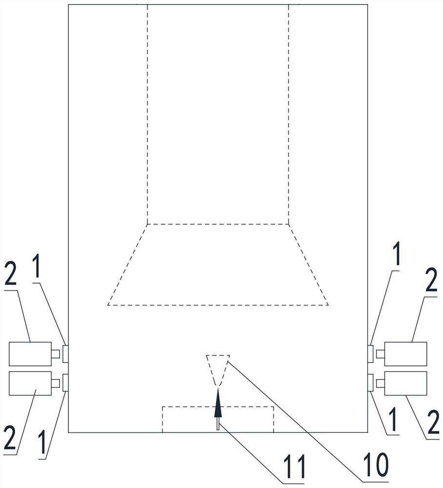
[0062]Seefigure 1 As shown, the infrared thermal imaging measuring device of the surface temperature of the wind tunnel test model provided herein, including the image processing system (not shown in the figure), four infrared windows 1, distributed over both sides opposite the wind tunnel test section. Wall, each side has two infrared window 1, and two infrared windows 1 are arranged at the axial intervals of the wind tunnel test section, and 1 in the high temperature region of the wind tunnel test model 10 and the low temperature area of ​​the low temperature area The inlet thermal imager 2 having different temperature measurement ranges, respectively, to achieve the surface temperature of different temperature regions of the wind tunnel test model 10, and the four infrared thermal imager 2 is placed in the corresponding support platform 3. The outer side of the infrared window 1 corresponds to the image processing system signal connection, the image processing sy...

Example Embodiment

[0085]Example 2

[0086]SeeFigure 13 As shown in the same, the second embodiment is substantially the same as that of the embodiment, the same is not described in the same, in which at least one infrared window 1 is disposed in the side wall of the wind tunnel test section through the texture lens barrel 8. While the temperature is measured, the flow of flow is also realized.

[0087]Since the texture lens barrel 8 has a certain length (generally 3 meters), the field of view of the infrared thermal imager 2 here will become smaller, but to increase the size of the infrared window 1 size, not only increase costs, It is also subject to the cause of wind tunnel on-site conditions and processing restrictions such as optical parts, increase technological risks. Based on this, in this preferred embodiment, seeFigure 14 withFigure 15 As shown, the infrared window 1 is fixed to the texture lens barrel 8 through the window fixing structure 9, and the window fixing structure 9 includes a shifting f...


PUM


Abstract

The invention relates to the technical field of wind tunnel test devices, in particular to an infrared thermal imaging measuring device for the surface temperature of a wind tunnel test model. The infrared thermal imaging measuring device comprises an image processing system and a plurality of infrared windows arranged on a wind tunnel test section, each infrared window is provided with an infrared thermal imager, the infrared thermal imagers are supported and fixed through a supporting platform, and the infrared thermal imagers are in signal connection with the image processing system. And thermal infrared imagers with different temperature measuring ranges are respectively and correspondingly arranged at the infrared windows corresponding to the high-temperature area and the low-temperature area of the wind tunnel test model. The infrared thermal imaging measuring device can simultaneously realize accurate measurement of transient temperatures of different surfaces and different temperature regions in one test, and the measuring efficiency and the measuring precision are improved.

Description

Technical field[0001]The present invention relates to the technical field of wind tunnel testing devices, and more particularly to an infrared thermal imaging measuring device for surface temperature of wind tunnel test model.Background technique[0002]Any object is only in an absolute zero, which is continuously radiated throughout. Since the temperature between the object is different or the temperature is different, the energy of their respective radiation is different. The infrared thermal imaging is imaging with the thermal contrast generated by this difference. It converted into an electrical signal by thermal radiant energy, and converted to a digital signal via A / D, and formed a subsequent infrared thermal imaging spectrum, and then tested to obtain a temperature distribution image of an object.[0003]Since the 1967 Swedish Aviation Research Institute, Thomann and Frisk first applied infrared thermal imaging techniques to wind tunnels, as a pneumatic test tool, infrared ther...

Claims


Application Information

Patent Timeline
IPC IPC(8): G01J5/02G01M9/04
CPCG01J5/0205G01M9/04
Inventor 李明石义雷李志辉李震乾
Owner 中国空气动力研究与发展中心超高速空气动力研究所
Why Eureka
Try Eureka