
Method for simulating and optimizing loading of a transport system

a transportation system and optimization method technology, applied in the field of freight transportation, can solve the problems of insufficient consideration, difficulty in implementing and exploiting the full potential of operators, and insufficient consideration of conventional constraints, in particular relating to the fuel consumption of car transporter vehicles,

Pending Publication Date: 2021-03-18
LOHR ELECTROMECANIQUE
View PDF19 Cites 2 Cited by
  • Summary
  • Abstract
  • Description
  • Claims
  • Application Information

AI Technical Summary

Benefits of technology

The invention relates to a method for simulating and optimizing the loading of vehicles, which can be used both on new and old transport systems. The method allows for the efficient and safe loading of vehicles based on parameters such as vehicle type, vehicle age, and load weight. The simulation and optimization tool provides a display for easy visualization of these parameters and helps to prevent accidents and damage to vehicles during loading. Overall, the invention improves operational efficiency and safety in vehicle loading.

Problems solved by technology

This therefore makes vehicle transport systems extremely complicated.
This gives rise to difficulties for operators as regards implementation and exploiting their fullest potential.
Furthermore, conventional constraints, in particular linked to the fuel consumption of car transporter vehicles, are not taken into account, or are not taken sufficiently into account, in these optimization problems.
This is also the case for the constraints linked to premature wear, for example of car transporter vehicles, which could result in a problem of unsuccessful or incomplete optimization.
Known methods cannot be used to identify the best possible imbrication.
Thus, these methods are complicated in their implementation and time-consuming and necessitate an in-depth knowledge of the craft.

Method used


Image

  • Method for simulating and optimizing loading of a transport system
  • Method for simulating and optimizing loading of a transport system
  • Method for simulating and optimizing loading of a transport system

Examples


Embodiment Construction

[0061]Structurally and functionally identical elements present on several distinct figures are provided with the same numerical or alphanumerical reference.

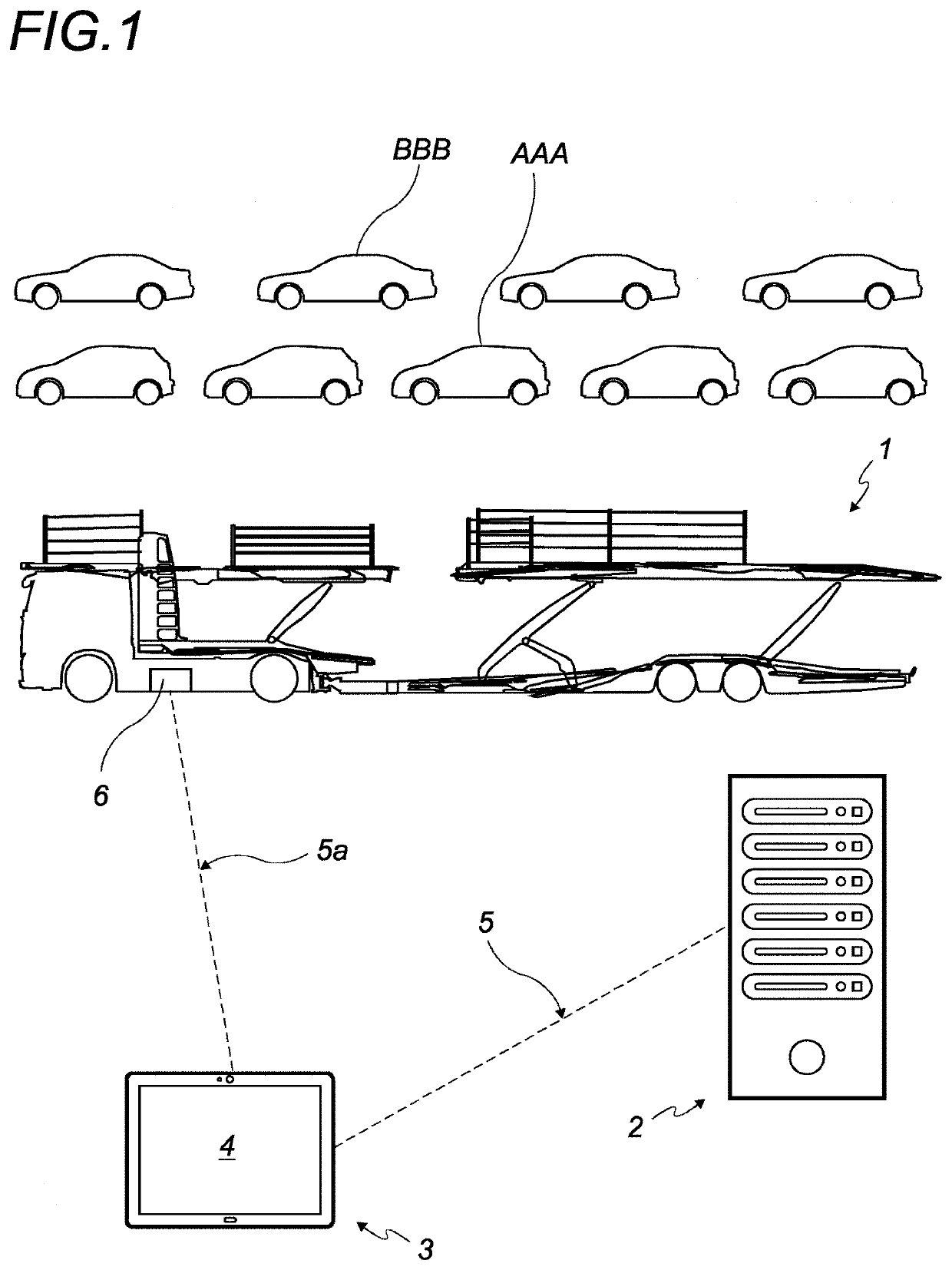
[0062]FIG. 1 is an example of a simplified diagram illustrating the simulation and optimization method according to the invention with implementation means. More particularly, reference will be made below to a loading system of the car transporter vehicle type 1 and to loads in the form of cars AAA and BBB. The invention is not limited to this particular type of loading system.

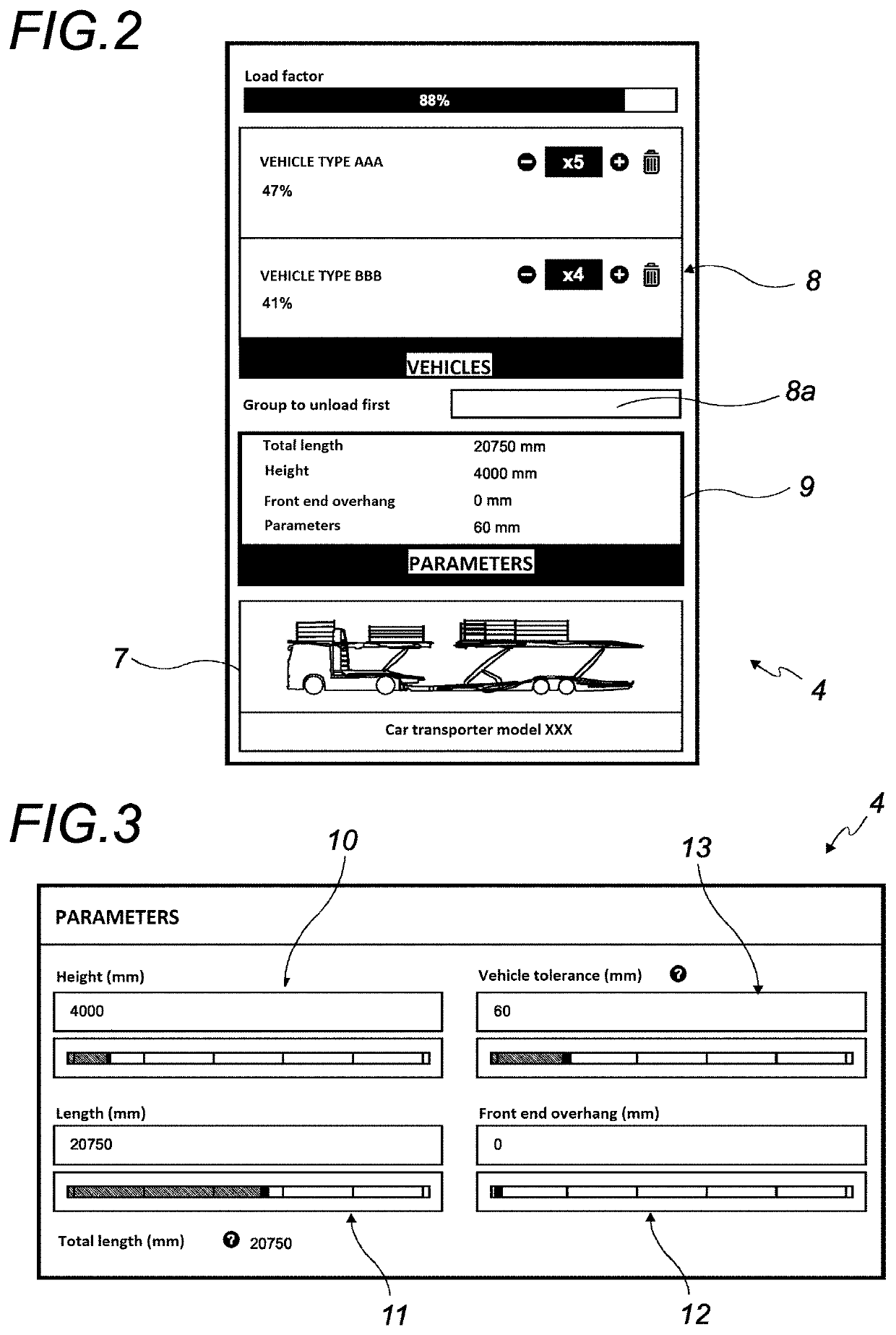
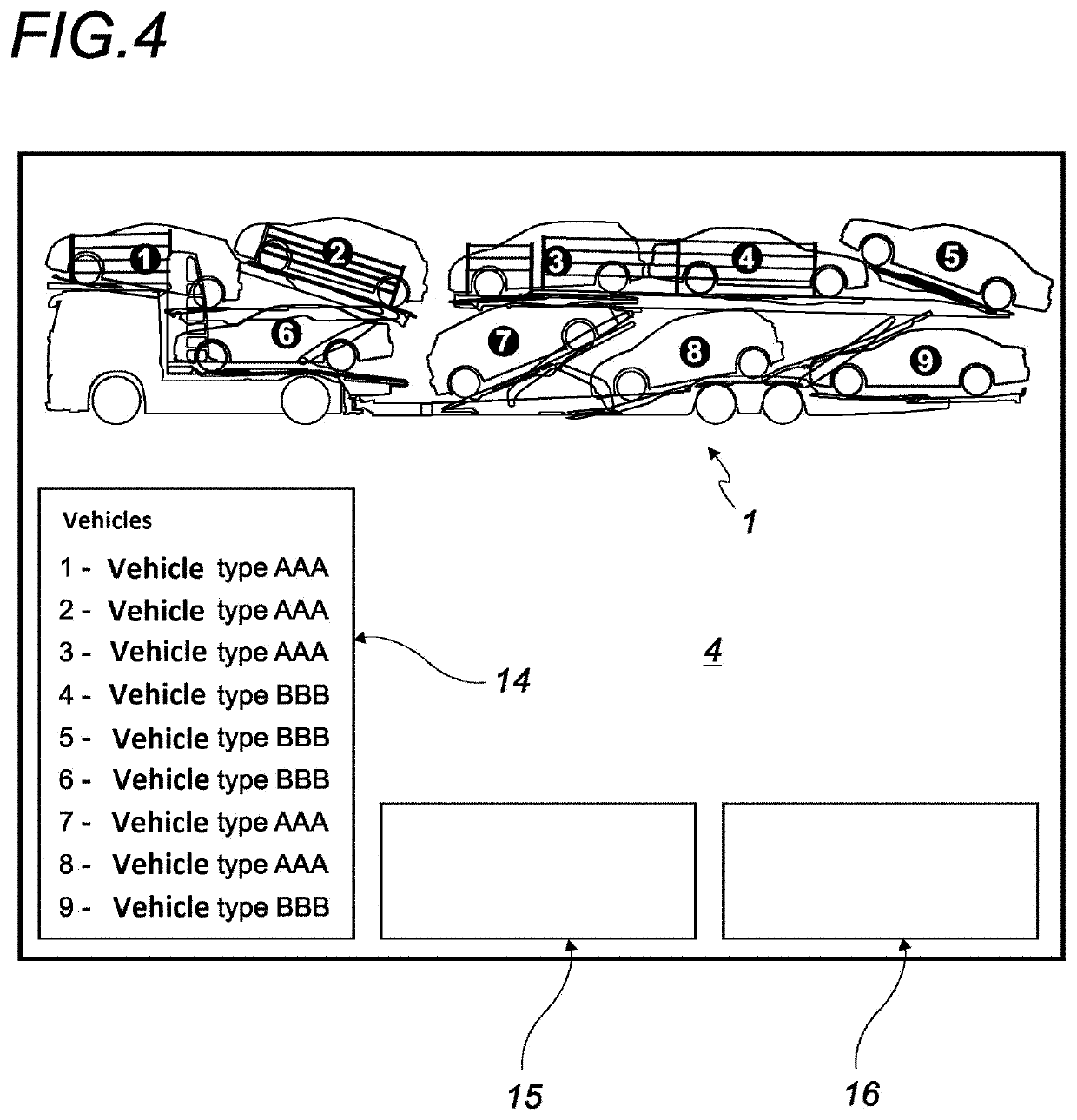
[0063]The method for simulating and optimizing loading according to the invention is carried out, for example, by means of a computer server 2 and a digital tool 3 of the tablet or smartphone type. The digital tool 3 advantageously comprises a touch screen 4.

[0064]In accordance with one exemplary embodiment, the invention is also based on a communications link 5, which is wireless, of the WIFI or GSM type between the computer server 2 and the digital tool 3...


PUM


Abstract

The invention concerns a method for simulating and optimizing loading of a system for transporting loads in order to determine an optimized loading plan. The method includes: a) inputting the previously defined structural and functional parameters of at least one transport system; b) inputting the number and the dimensional and weight parameters of the loads to be transported; c) inputting the spacing between the loads from previously defined values; d) inputting the route and / or the destination of the load to select the previously defined legal constraints during transport; e) carrying out an optimization calculation in real time, taking into account the parameters and constraints of steps a), b), c) and d) to simulate at least one optimized loading plan consistent with all of the constraints; and f) presenting an optimized loading calculated in e) or approximating an initial loading request.

Description

CROSS-REFERENCE TO RELATED APPLICATIONS[0001]This application is a § 371 filing of PCT application PCT / FR2018 / 053275 filed on Dec. 13, 2018, which claims priority from French application FR 1762037 filed on Dec. 13, 2017. The disclosures of these applications are included by reference herein in their entirety.BACKGROUNDField of the Invention[0002]The present invention relates to the general field of the transport of freight and in particular to the transport of vehicles. The invention concerns a method for simulating and optimizing the payload of a system for the transport of vehicles, for example by road, rail or sea, with or without containers. This method enables a user to obtain an optimized loading plan starting from a collection of vehicles to be transported and a transport system which, for example, includes a car transporter vehicle. The term “imbrication” will be used below to designate a loading plan of this type.[0003]The invention also concerns a loading method per se.[0...

Claims


Application Information

Patent Timeline
Patent Type & Authority Applications(United States)
IPC IPC(8): G06Q10/08B60P3/08B60P3/07G01C21/34G01C21/36G05B19/4155
CPCG06Q10/087B60P3/08B60P3/07G01C21/3453G05B2219/50362G05B19/4155B60K2370/152B60K2370/16G01C21/3605G06Q10/08
Inventor WINCKEL, DAVIDMAURIN, BENJAMINKARNOUKIAN, MARC
Owner LOHR ELECTROMECANIQUE
Learn More