
Voltage doubling variable frequency drive

Inactive Publication Date: 2021-03-18
MEDAGAM PEDA V +2
View PDF2 Cites 0 Cited by
  • Summary
  • Abstract
  • Description
  • Claims
  • Application Information

AI Technical Summary

Benefits of technology

This patent describes a control method for an active front end variable frequency drive (VFD) that improves its performance. The method uses adaptive hysteresis control techniques to maintain a constant average switching frequency, boost output voltage, control input currents to reduce harmonics, and achieve a near unity power factor. The method also allows the VFD to operate in an o regenerative mode. The technical effects of this method include improved performance, efficiency, and reduced emissions.

Problems solved by technology

A variable frequency drive using such a diode bridge draw non-sinusoidal, non-linear input currents from the AC power line and cause several detrimental effects.
Due to the substantial irregularities that the diode bridge causes to the power grid, substantial passive filters must be placed between the variable frequency drive and the power grid.
The passive filters that meet IEEE-519 standards are expensive and not readily available.
They also have disadvantages such as resonance with the utility, large size, and weight, and may not be suitable for variable loads.
This regenerative power is traditionally wasted as heat using dynamic braking resistors.
However, Dynamic braking resistors add complexity and expense to a variable frequency drive installation.
Further, as the motor is generating additional heat, more cooling is needed, and excess heat is known to damage electrical and mechanical parts.
Diode rectifier converters cannot directly boost the incoming 240 volts to 460 volts.
The unbalanced three-phase AC voltage is also very common in rural areas, with such unbalanced voltages diode bridge variable frequency drives drawing unbalanced currents from the AC source and causing higher stress on VFD components.
An issue with traditional hysteresis current control method is that it uses a fixed hysteresis band.
A fixed band hysteresis control causes the switching frequency to vary widely depending on the load and instantaneous magnitude of the current, causing unpredictable EMI radiations and challenges.

Method used


Image

  • Voltage doubling variable frequency drive
  • Voltage doubling variable frequency drive
  • Voltage doubling variable frequency drive

Examples


Embodiment Construction

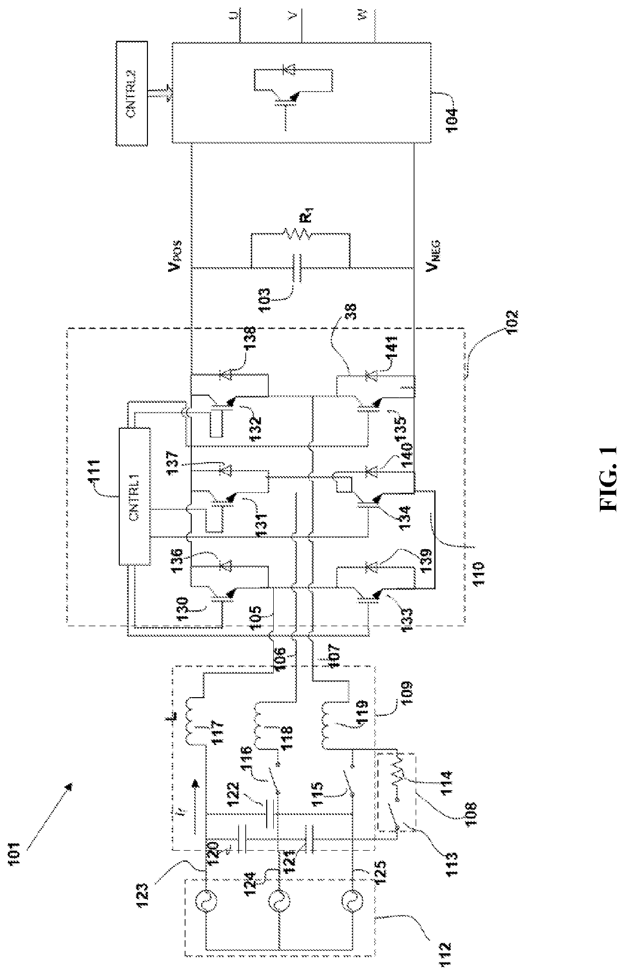
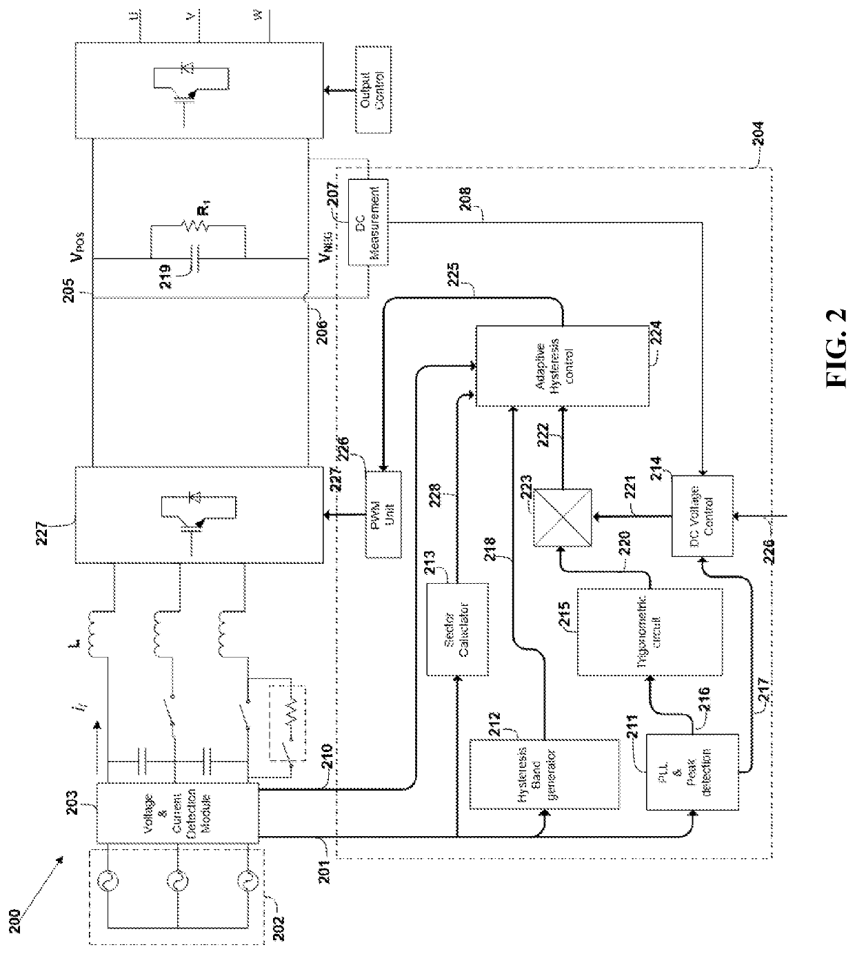
[0021]Referring to FIG. 1, a regenerative variable frequency drive 101, embodying the features of the present invention, includes an active converter 102, a DC bus 103 connects to the converter 102, and inverter 104 connected to the DC bus 103. The converter 102 includes first, second, and input lines 105, 106 and 107, a precharging circuit 108, an input filter 109, an active rectifier 102 and a controller 111. The first, second and third input lines 105, 106 and 107 connect to a three-phase AC source 112. Generally, source 112 will be a utility power grid. In the United States, the source 112 will typically provide power at 240V at 60 Hz.

[0022]The precharging circuit 108 connects along the second and third input line 106, 107 and includes a relay switch 113 connected in series to a resistor 114, and a contactor switches 115 and 116 connected in parallel to the relay switch 113 and the resistor 114. During startup of the drive 101, the relay switch 113 is closed, and the contactor s...


PUM


Abstract

Briefly, a voltage doubling variable frequency drive includes an active converter connected to a DC bus that is connected to a first inverter that converts DC power to variable frequency, three-phase AC power, and variable frequency, three-phase AC power to DC power, and to a second inverter that converts DC power to three-phase AC sine wave power. The converter converts single-phase AC power to DC power and DC power to single-phase AC power and maintains a selected voltage on the DC bus. The converter has an active rectifier and a controller that drives the rectifier with a pulse width modulation according to a switching scheme that switches the rectifier according to an adaptive hysteresis control to maintain constant switching.

Description

TECHNICAL FIELD[0001]The present invention relates to a three-phase variable frequency drive with a voltage doubling converter on the front side that converts three-phase AC input to DC with regenerative capability. The DC can then be converted to a three phase output.BACKGROUND ART[0002]Three-phase variable frequency drives are commonly used in speed control for alternating current (AC) motors. Variable frequency drives generally include a diode rectifier, that converts AC power to direct current (DC) power, connected through a DC bus to an inverter that supplies a three phase output, variable frequency AC power to a three-phase motor.[0003]A variable frequency drive using such a diode bridge draw non-sinusoidal, non-linear input currents from the AC power line and cause several detrimental effects. IEEE 519 standard recommends limits of 5-8% total harmonic distortion (THD) to protect assets on the power grid. Due to the substantial irregularities that the diode bridge causes to th...

Claims


Application Information

Patent Timeline
IPC IPC(8): H02M5/458H02P27/08
CPCH02M5/4585H02P27/08H02M1/4216H02M1/126H02M1/36Y02B70/10
Inventor MEDAGAM, PEDA VYANG, JACKKINGSBURY, NICHOLAS R
Owner MEDAGAM PEDA V
Learn More