
High efficiency microwave amplifier

Active Publication Date: 2011-01-04
TYCO HEALTHCARE GRP LP
View PDF108 Cites 72 Cited by
  • Summary
  • Abstract
  • Description
  • Claims
  • Application Information

AI Technical Summary

Benefits of technology

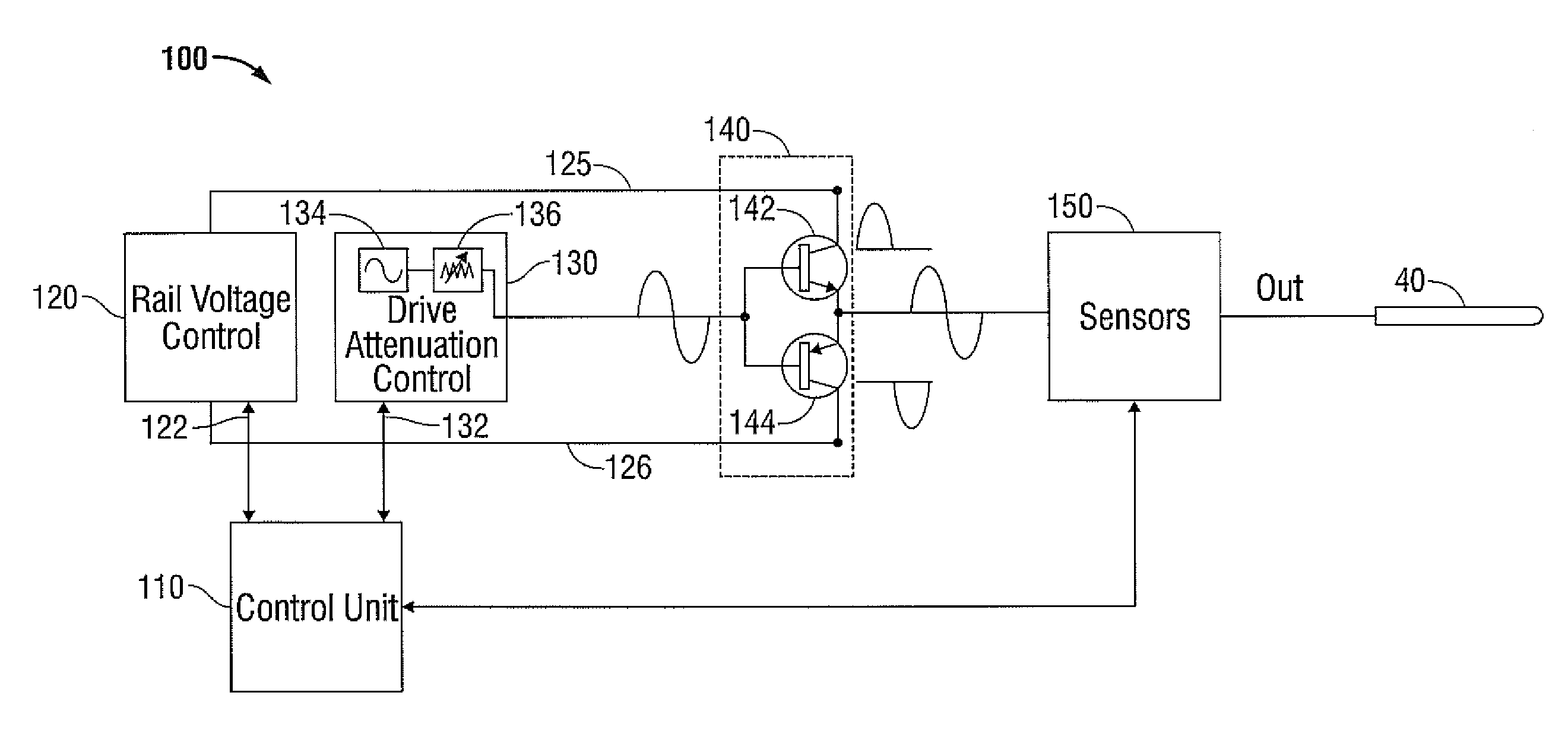
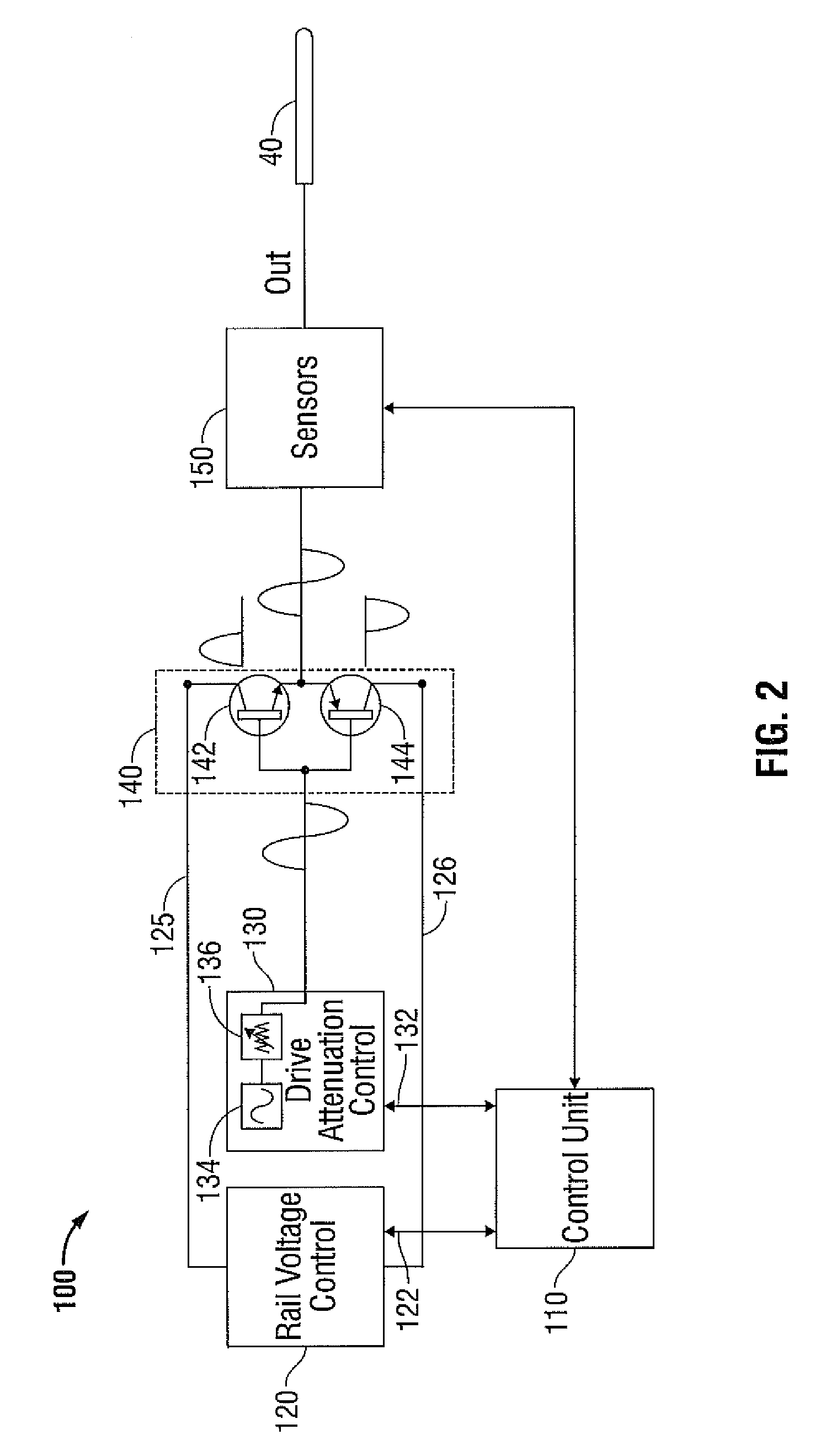
[0009]The present disclosure provides a method and apparatus for an improved microwave ablation amplifier having a push-pull configuration which exhibits improved efficiency over a wide range of power output levels. A generator in accordance with the present disclosure may also exhibit reduced harmonics in the high-power surgical output signal, which reduces undesirable radiofrequency interference. In accordance with the present disclosure, a low power input signal is maintained at a constant, relatively high level, while the output level of the amplifier is adjusted, at least partially, by varying the supply voltage (e.g., the “rail” voltage) of a push-pull class B amplifier output stage. At least one LDMOS (laterally diffused metal oxide semiconductor) transistor, such as without limitation, a BLC6G10LS-160, manufactured by NXP Semiconductors of Eindhoven, The Netherlands, may be included in the amplifier output stage.
[0011]The amplifier control unit, in response to an at least one sensor signal, dynamically varies an operating parameter, e.g., a rail voltage and / or an input level, to achieve efficient and stable operation of the generator over a range of output power levels. The control unit may impose a rail voltage minima on the presently disclosed amplifier. For example, the rail voltage may be held to greater than about 14V in order to avoid undesirable increases in the internal capacitance of an LDMOS device, such as without limitation a BLC6G10LS-160 UHF power LDMOS transistor manufactured by NXP B.V. of The Netherlands, which may cause the amplifier to detune and / or become unstable. The minimum rail voltage is dependent upon the LDMOS utilized in an embodiment, and embodiments utilizing LDMOS devices other than a BLC6G10LS-160 may require a minimum rail voltage that is greater than, or less than, about 14V. In another example, at a lower portion of the amplifier's operating power, the controller may be configured to increase power output by first causing the drive attenuation control unit to output a signal of sufficient amplitude to cause the LDMOS device(s) to operate outside the linear operating region thereof, thereby achieving improved operating efficiency. When the LDMOS devices are operating outside the linear region, output power may be further increased by increasing the rail voltage. The drive signal may be correlated to the rail voltage, e.g., the drive signal may be increased proportionally to the rail voltage.

Problems solved by technology

Commonly used microwave power amplifiers are known to be inefficient.
The resulting heat becomes difficult to manage and may require the use of bulky and costly cooling systems, e.g., fans and heat sinks.
Additionally, the excess heat may cause thermal stress to other components of the generator, shortening generator life, decreasing reliability, and increasing maintenance costs.
Additionally, a class AB amplifier may exhibit crossover distortion that introduces undesirable harmonics into the surgical signal, which are known to cause radiofrequency interference in excess of acceptable limits.

Method used


Image

  • High efficiency microwave amplifier
  • High efficiency microwave amplifier
  • High efficiency microwave amplifier

Examples


Embodiment Construction

[0031]Particular embodiments of the present disclosure are described hereinbelow with reference to the accompanying drawings; however, it is to be understood that the disclosed embodiments are merely exemplary of the disclosure, which may be embodied in various forms. Well-known functions or constructions are not described in detail to avoid obscuring the present disclosure in unnecessary detail. Therefore, specific structural and functional details disclosed herein are not to be interpreted as limiting, but merely as a basis for the claims and as a representative basis for teaching one skilled in the art to variously employ the present disclosure in virtually any appropriately detailed structure.

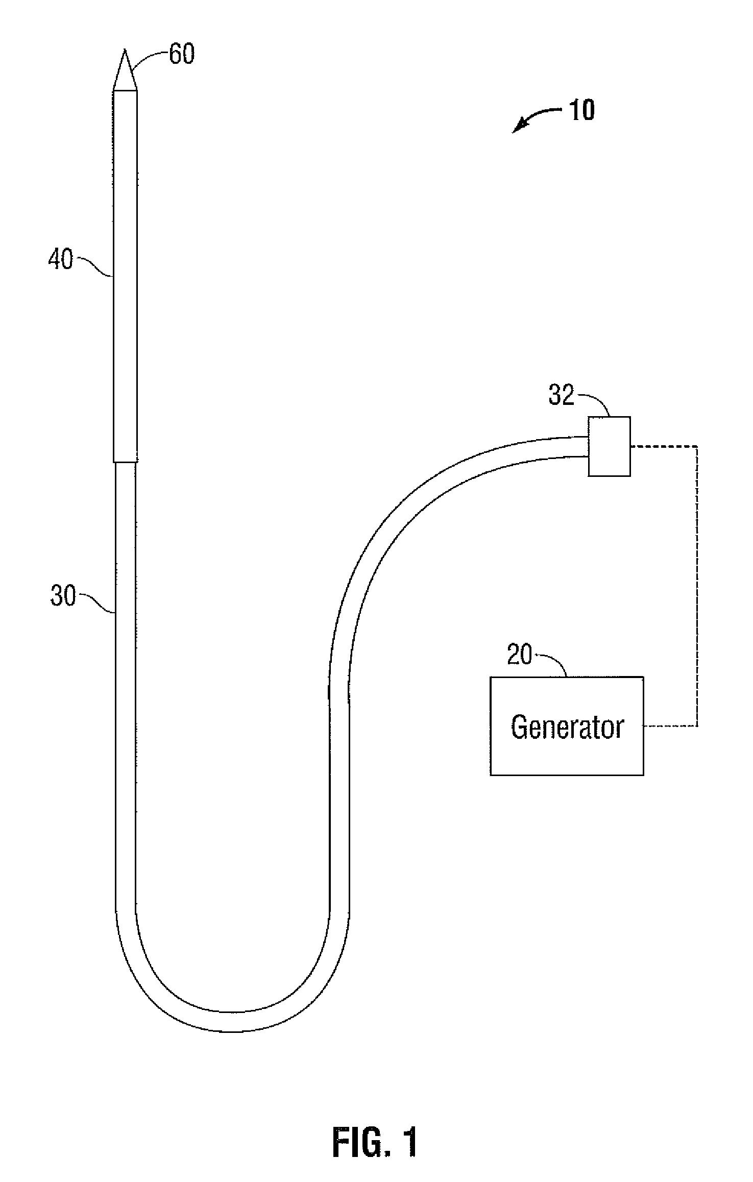
[0032]FIG. 1 shows an embodiment of a microwave ablation system 10 in accordance with the present disclosure. The microwave ablation system 10 includes an electromagnetic surgical ablation probe 40 connected by a cable 30 to a connector 32, which may further operably connect the probe 40 to...


PUM


Abstract

Disclosed is an apparatus and method for operating a microwave amplifier with improved efficiency and reduced harmonic emissions. The disclosed amplifier includes a variable rail voltage supply and a variable input drive stage. A controller continually monitors the amplifier output and adjusts the rail voltage and input drive signal to achieve high efficiency and low harmonic emissions. The amplifier may include a dynamic bias controller configured to operate the gain elements outside the linear region. Efficiencies of over 70% may be achieved by the disclosed amplifier.

Description

BACKGROUND[0001]1. Technical Field[0002]The present disclosure relates to systems and methods for providing energy to biological tissue and, more particularly, to improved apparatus and methods for amplifying microwave energy for use during surgical procedures.[0003]2. Background of Related Art[0004]Energy-based tissue treatment is well known in the art. Various types of energy (e.g., electrical, ultrasonic, microwave, cryogenic, thermal, laser, etc.) are applied to tissue to achieve a desired result. Electrosurgery involves application of high radio frequency electrical current to a surgical site to cut, ablate, coagulate or seal tissue. In monopolar electrosurgery, a source or active electrode delivers radio frequency energy from the electrosurgical generator to the tissue and a return electrode carries the current back to the generator. In monopolar electrosurgery, the source electrode is typically part of the surgical instrument held by the surgeon and applied to the tissue to b...

Claims


Application Information

Patent Timeline
IPC IPC(8): H03G3/30
CPCH03F3/19H03F1/0233H03F3/26
Inventor BEHNKE, ROBERT J.
Owner TYCO HEALTHCARE GRP LP
Learn More