

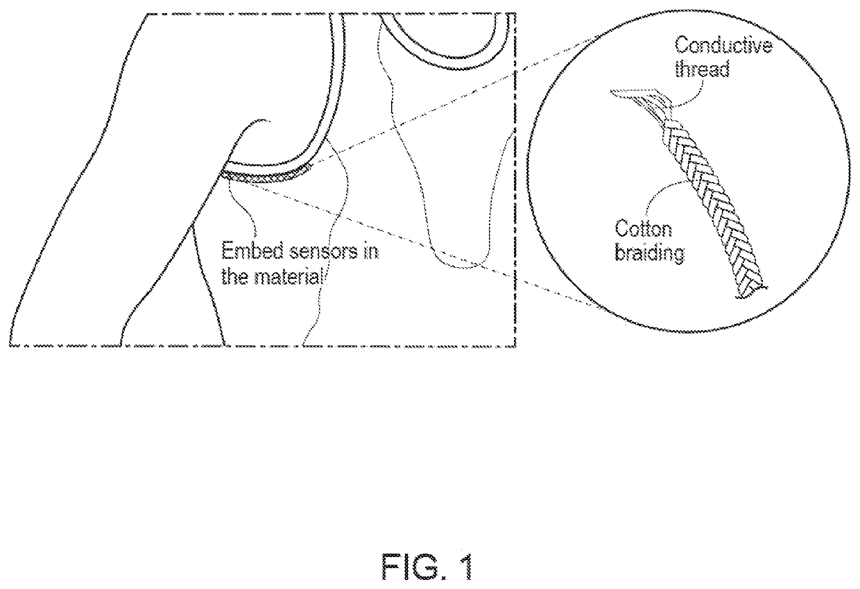
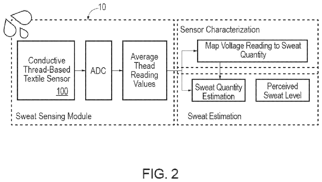
Textile Sensor Assemblies
a technology of textile sensors and assemblies, applied in the field of textile sensor assemblies, can solve the problems of inaccurate reading or discomfort of sensitive and hairy skin, inability to guarantee the stability of contact between cotton braids and conductive threads, and hypothermia, or even death, and achieve the effect of robust perspiration level estimation
- Summary
- Abstract
- Description
- Claims
- Application Information
AI Technical Summary
Benefits of technology
Problems solved by technology
Method used
Image

Examples
embodiment 1
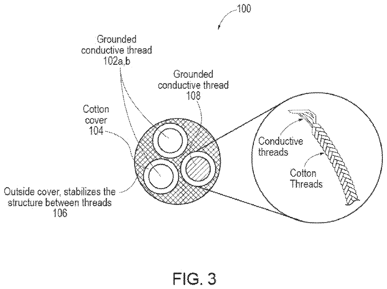
[0110] A sensor, comprising: a first textile assembly having a first conductive element and a first outer sheath that surrounds the first conductive element, the first outer sheath formed from a first non-conductive material that is configured to transport moisture through the first outer sheath; and a second textile assembly having a second conductive element and a second outer sheath that surrounds the second conductive element, the second outer sheath formed from a second non-conductive material that is configured to transport moisture through the second outer sheath, the first and second outer sheaths maintaining a separation between the first conductive element and the second conductive element along a length of the sensor.
[0111]Embodiment 2. The sensor of Embodiment 1, further comprising an outer cover that at least partially encases the first and second textile assemblies.
[0112]Embodiment 3. The sensor of Embodiment 2, wherein the outer cover is a knitted structure, a woven s...
embodiment 4
[0113] The sensor of Embodiment 1, wherein the first non-conductive material and the second non-conductive material comprise at least one of a knitted structure, a woven structure, a braided structure, and a knotted structure.
embodiment 5
[0114] The sensor of Embodiment 1, wherein the first outer sheath is in contact with the second outer sheath.
PUM
| Property | Measurement | Unit |
|---|---|---|
| weight difference | aaaaa | aaaaa |
| voltage | aaaaa | aaaaa |
| length | aaaaa | aaaaa |
Abstract
Description
Claims
Application Information