Prosthesis with Anti-paravalvular leakage component including a one-way valve

US20210085453A1Active Publication Date: 2021-03-25MEDTRONIC INC

Image

  • Prosthesis with Anti-paravalvular leakage component including a one-way valve
  • Prosthesis with Anti-paravalvular leakage component including a one-way valve
  • Prosthesis with Anti-paravalvular leakage component including a one-way valve

Examples


Embodiment Construction

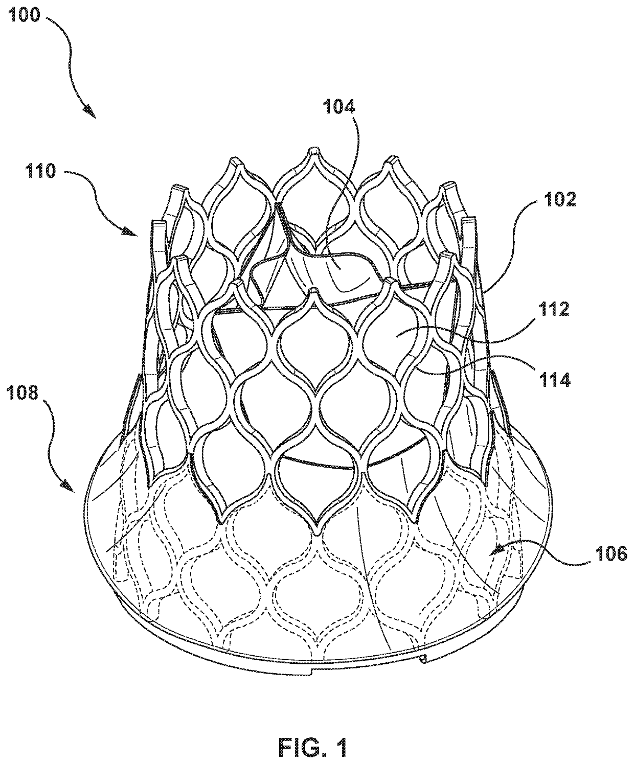
[0028]Specific embodiments of the present invention are now described with reference to the figures, wherein like reference numbers indicate identical or functionally similar elements. The terms “distal” and “proximal” are used in the following description with respect to a position or direction relative to blood flow. “Distal” and “distally” refer to positions in the downstream direction with respect to the direction of blood flow. “Proximal” and “proximally” refer to positions in an upstream direction with respect to the direction of blood flow.

[0029]The following detailed description is merely exemplary in nature and is not intended to limit the invention or the application and uses of the invention. Although the description of embodiments hereof are in the context of treatment of a native heart valve such as an aortic valve, the invention may also be used at other heart valve locations and in any other body passageways where it is deemed useful. Furthermore, there is no intentio...


PUM


Abstract

A transcatheter prosthesis includes a stent, a prosthetic valve component, and an anti-paravalvular leakage component. The anti-paravalvular leakage component is coupled to the stent and includes an inner skirt, an outer wrap, a cavity, an opening, and a one-way valve. The inner skirt is disposed on an inner surface of the stent and has an inflow end and a downstream end. The outer wrap is disposed around an outer surface of the stent and has an inflow end coupled to the inflow end of the inner skirt and a downstream end. The cavity is formed between an outer surface of the inner skirt and an inner surface of the outer wrap. An opening is disposed between the inner skirt and the outer wrap. The one-way valve includes a flap at the opening configured to open to allow blood flow into the cavity but prevent blood flow out of the cavity.

Description

FIELD OF THE INVENTION[0001]The invention relates generally to prostheses for intervascular delivery. More particularly, the present invention relates to valve prostheses with an anti-paravalvular leakage component to assist in the prevention of paravalvular leakage at the deployed valve prosthesis.BACKGROUND OF THE INVENTION[0002]The human heart is a four chambered, muscular organ that provides blood circulation through the body during a cardiac cycle. The four main chambers include the right atria and right ventricle which supplies the pulmonary circulation, and the left atria and left ventricle which supplies oxygenated blood received from the lungs to the remaining body. To ensure that blood flows in one direction through the heart, atrioventricular valves (tricuspid and mitral valves) are present between the junctions of the atria and the ventricles, and semi-lunar valves (pulmonary valve and aortic valve) govern the exits of the ventricles leading to the lungs and the rest of ...

Claims


Application Information

Patent Timeline
25 Mar 2021
Publication
US20210085453A1
IPC
A61F2/24
CPC
A61F2/2418; A61F2/2433; A61F2210/0014; A61F2250/0069; A61F2/2463; A61F2/2466; A61F2/2445; A61F2250/0003
Inventors
CLAGUE, CYNTHIA; MENK, ANA