Injection molding machine and flash prevention method

Active Publication Date: 2021-03-25
NISSEI PLASTIC IND CO LTD
View PDF0 Cites 0 Cited by
  • Summary
  • Abstract
  • Description
  • Claims
  • Application Information

AI Technical Summary

Benefits of technology

The present invention aims to improve the injection molding process by adjusting the mold clamping force based on the mold displacement or injection peak pressure and position. This results in flash-free molded articles, reduced energy needed for mold clamping, and increased lifespan of the injection molding machine and mold.

Problems solved by technology

However, the repeated application of an excessive mold clamping force to the mold accelerates degradation of the mold.
The application of the excessive mold clamping force also causes an unnecessary increase in energy use.

Method used


Image

  • Injection molding machine and flash prevention method
  • Injection molding machine and flash prevention method
  • Injection molding machine and flash prevention method

Examples


Embodiment Construction

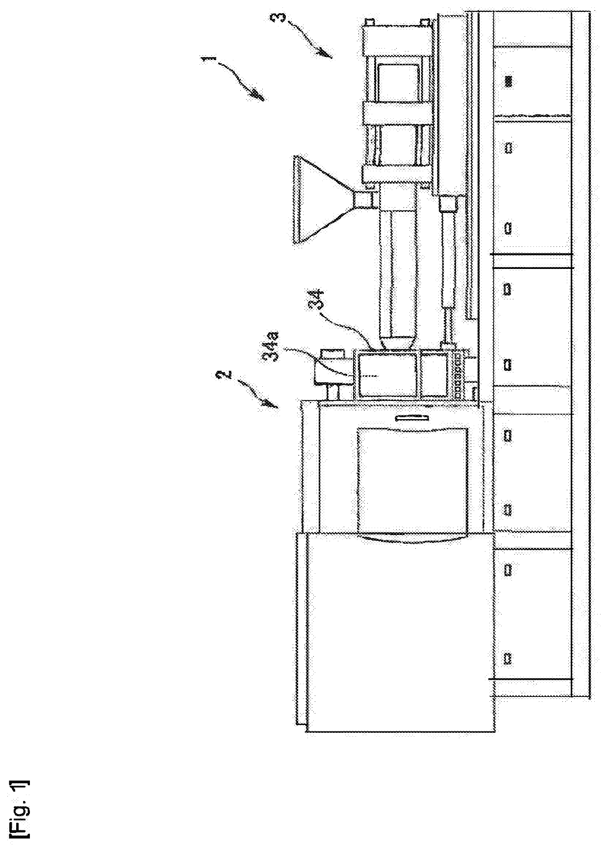
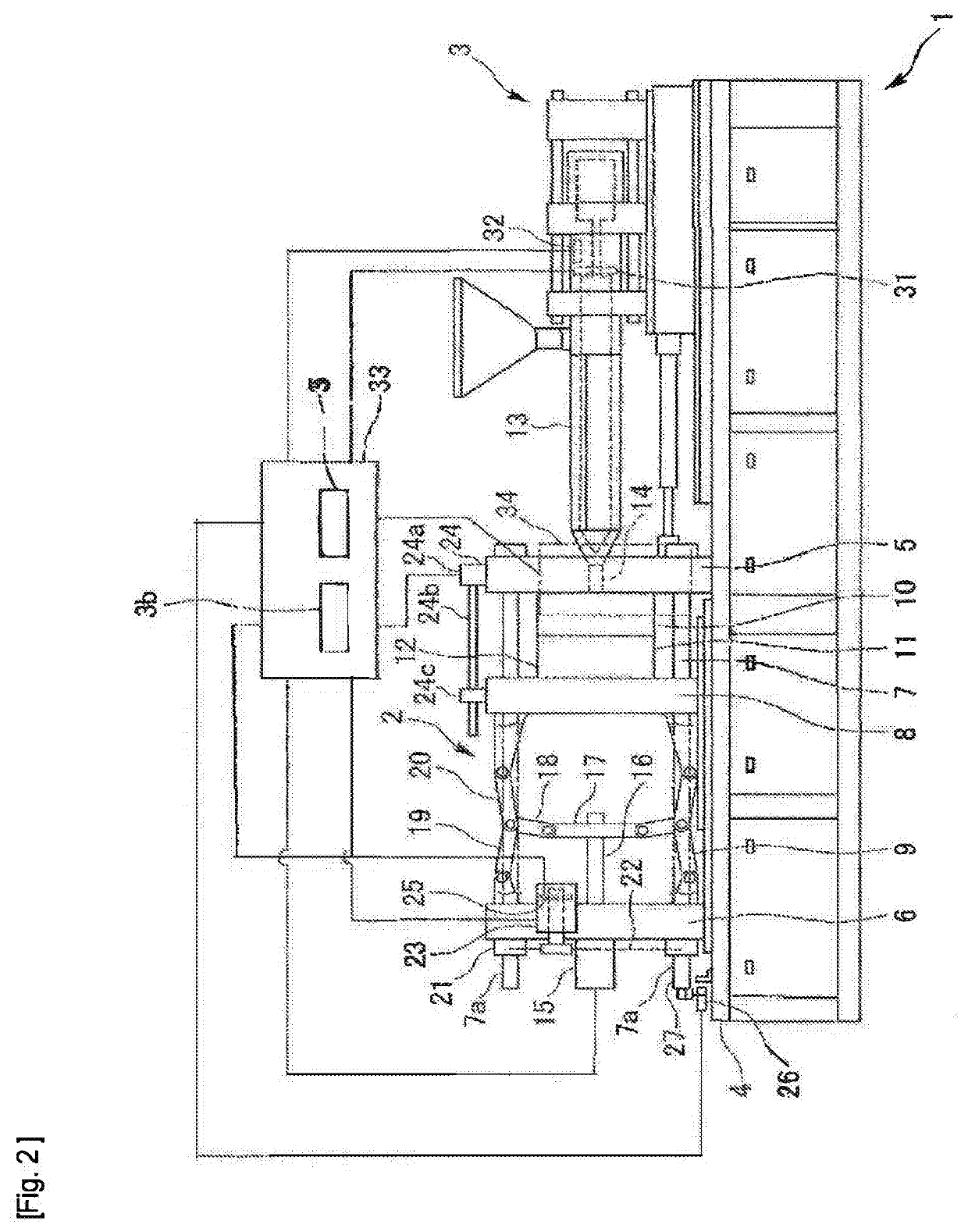
[0032]The present invention will be described in detail on the basis of an embodiment shown in FIGS. 1 to 4. FIGS. 1 and 2 show an injection molding machine 1 that is the embodiment of the present invention. The injection molding machine 1 includes a toggle type mold clamping unit 2 and an injection unit 3. A molding cycle includes mold closing, mold clamping, injection filling of a molten resin, measurement, mold opening, and removal of a molded article. The injection molding machine 1 can perform automatic operation of repeating the molding cycle to manufacture molded articles.

(Mold Clamping Unit)

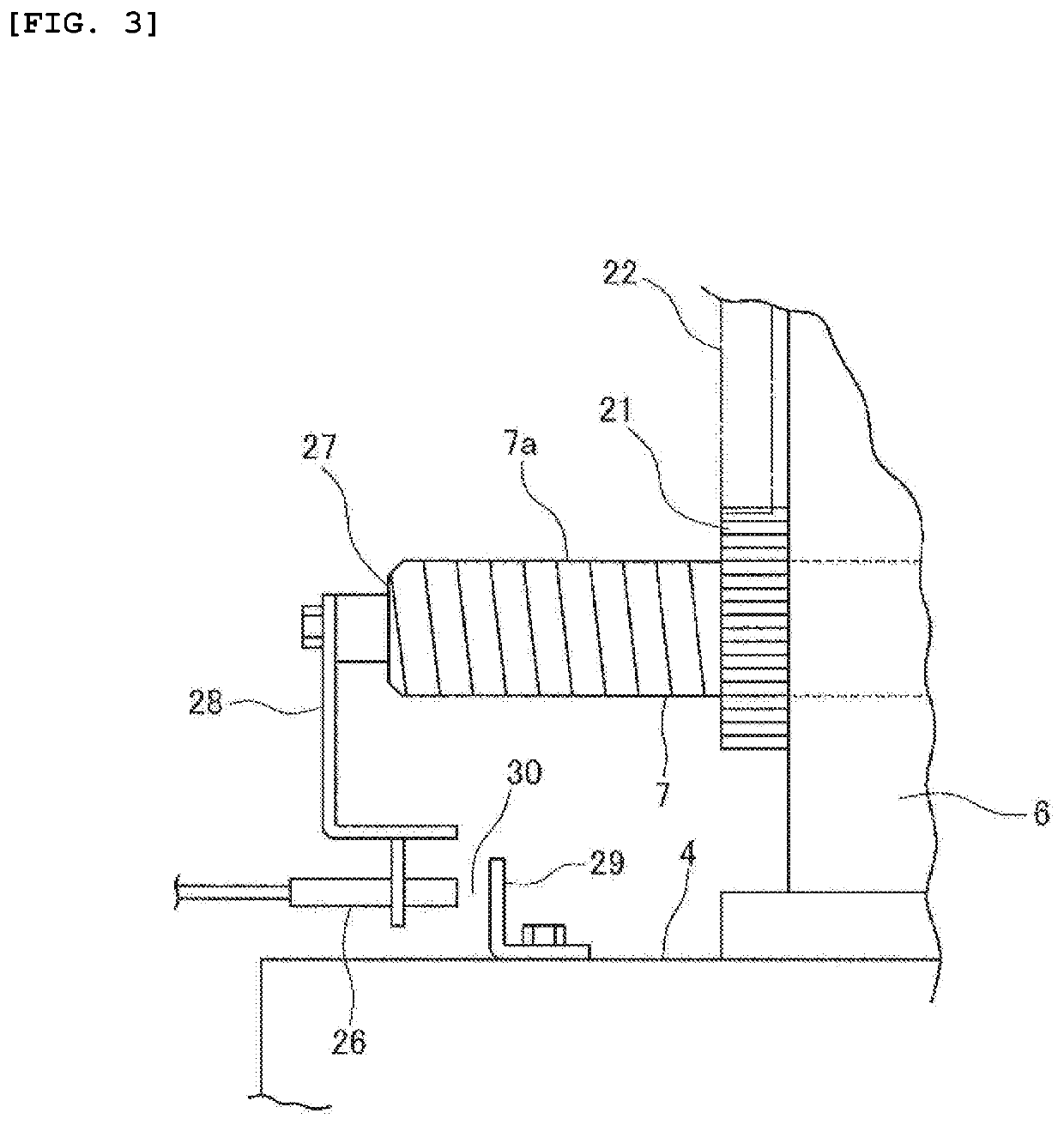
[0033]The toggle type mold clamping unit 2 includes a stationary platen 5, a pressure-receiving platen 6, tie bars 7, and a movable platen 8. The stationary platen 6 is fixed onto a base 4. The pressure-receiving platen 6 is installed movably over the base 4. The tie bars 7 are located across the stationary platen 5 and the pressure-receiving platen 6. The tie bars 7 are fixed to the stat...


PUM

PropertyMeasurementUnit
Forceaaaaaaaaaa
Pressureaaaaaaaaaa
Distanceaaaaaaaaaa

Abstract

When an injection molding machine performs molding, the mold clamping force on the mold is adjusted on the basis of a mold displacement of the mold or the injection peak pressure and injection foremost position so that the molding is performed without causing flash and by an appropriate mold clamping force with which energy can be reduced. The amount of mold displacement and also the injection peak pressure and the injection foremost position are monitored during automatic operation. If there occurs no mold displacement change exceeding a threshold or if there occurs no injection peak pressure anomaly or injection foremost position anomaly exceeding thresholds, the automatic operation is continued. If the mold displacement change occurs or if the injection peak pressure anomaly and the injection foremost position anomaly occur, the operation of the injection molding machine is stopped.

Description

BACKGROUND OF THE INVENTION1. Field of the Invention[0001]The present invention relates to an injection molding machine and a flash prevention method.2. Description of the Related Art[0002]There has conventionally been an injection molding machine including a mold clamping unit and an injection unit. The mold clamping unit includes tie bars located across a stationary platen fixed onto a base and a pressure-receiving platen movable over the base. The tie bars are fixed to and supported by the stationary platen at one end each. The pressure-receiving platen is coupled to the other ends of the tie bars in a manner so that its position can be adjusted with respect to the tie bars. The movable platen is attached between the stationary platen and the pressure-receiving platen movably along the tie bars. A toggle mechanism is built in between the pressure-receiving platen and the movable platen. A mold located between the movable platen and the stationary platen is closed and a mold clamp...

Claims


Application Information

Patent Timeline
IPC IPC(8): B29C45/76B29C45/77
CPCB29C45/768B29C45/77B29C45/7613B29C2945/76381B29C2945/76919B29C2945/76163B29C2945/76287B29C2945/76006B29C45/7653B29C45/80B29C45/66B29C45/0025B29C2945/76498B29C2945/76581B29C45/84B29C45/661B29C45/766B29C2945/76943B29C2945/76859B29C2945/76862B29C2945/76665B29C2945/76732B29C2945/76505B29C2945/76096B29C2945/76234
Inventor HAKODA, TAKASHIOGASAWARA, MITSUHIRO
Owner NISSEI PLASTIC IND CO LTD
Why Eureka
Try Eureka