System and method for refrigerant management in an electric vehicle

a technology for electric vehicles and refrigerant, applied in vehicle components, vehicle heating/cooling devices, transportation and packaging, etc., can solve the problems of insufficient refrigerant volume to operate the compressor, compressor in danger of failure, etc., and achieve the effect of preventing damage or failure of the compressor

Active Publication Date: 2021-03-25
JAGUAR LAND ROVER LTD
View PDF0 Cites 2 Cited by
  • Summary
  • Abstract
  • Description
  • Claims
  • Application Information

AI Technical Summary

Benefits of technology

[0021]In certain embodiments, the presence of an accumulator allows for control of vapour quality in the system.
[0035]In certain embodiments, the shut off valve in line between the heat pump condenser and the accumulator is closed in the cold start mode when the sensor detects one or both of: a non-superheated refrigerant at the compressor inlet and a temperature gradient equal to or less than 3 Kelvin between ambient and the compressor inlet. In this way, once the conditions for initiating the cold start mode are no longer detected by the system, the valve allowing reverse refrigerant flow between the heat pump condenser and the accumulator (or compressor) is closed. The system is then ready for operation in either the heating or the cooling mode as required. If the inlet to the compressor is warmer than ambient (e.g. the ambient air around the system), or at least less than 3 Kelvin colder, the refrigerant in the system is likely to have moved or pooled in the heat pump condenser (or the heat pump condenser and the evaporator / dehumidifier). If the compressor were to be actuated, there may be insufficient refrigerant at the compressor to prevent damage or failure of the compressor. In effect, in such an environment, the refrigerant is stuck in the components of the system closest to the ambient environment. The refrigerant management system of the invention is operable to initiate the cold start mode to move refrigerant in a temporary reverse flow from the heat pump condenser or the accumulator (or the compressor). Thereafter, the heating or the cooling mode can be initiated without danger of damage or failure of the compressor.

Problems solved by technology

When the system is started and the refrigerant compressor first operated after a period of being idle, if the refrigerant has pooled away from the compressor such as may happen in cold ambient conditions, there may be insufficient refrigerant volume to operate the compressor when the heat pump circuit is engaged.
In such circumstances, the compressor is in danger of failure.

Method used


Image

  • System and method for refrigerant management in an electric vehicle
  • System and method for refrigerant management in an electric vehicle
  • System and method for refrigerant management in an electric vehicle

Examples


Embodiment Construction

[0071]Wherever possible, like reference numerals are used to depict similar features throughout.

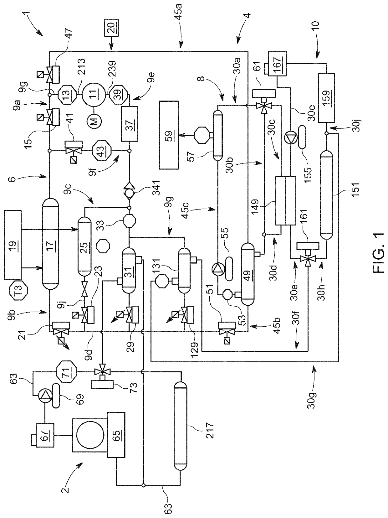
[0072]As shown in FIG. 1, the heat flux management system 1 for an electric vehicle 150 (see FIG. 6) comprises a refrigeration cycle refrigerant circuit 6 and a heat pump circuit 4. The components are indicated in the flow path of a fluid during operation within the respective circuits. When used herein “upstream” and “downstream” relate to the direction in which fluid will flow in the system.

[0073]In FIG. 1, the refrigeration cycle refrigerant circuit 6 comprises a refrigerant line 9a arranged to fluidly connect the compressor 11, a pressure and temperature sensor 13 and a shut-off valve 15 to an external air-refrigerant heat exchanger 17 operable as a heat pump condenser and thermally connected to a heat source, being ambient air 19; a second refrigerant line 9b arranged to fluidly connect the external heat exchanger 17 operable as a heat pump condenser and an expansion valve 21 associa...


PUM


Abstract

Embodiments of the present invention provide a refrigerant management system (10) in a heat flux management system (1) for an electric vehicle (150) and a method of refrigerant management, the system comprising a vehicle air conditioning circuit comprising a heat pump circuit (4) with a heating function and a refrigeration cycle refrigerant circuit (6), the air conditioning circuit comprising a heat pump condenser (17) in thermal communication with a heat source (19), a refrigerant evaporator (25) in thermal communication with the heat source (19), an evaporator (31) associated with an expansion valve (29), and a refrigerant compressor (11), wherein the components are fluidly connected to one another by a refrigerant line (9), an accumulator (37) fluidly coupled in the refrigerant line downstream of the heat pump condenser (17), the refrigerant evaporator (25) and evaporator (31) and upstream of the refrigerant compressor (11),wherein the air conditioning circuit is switchable between a heating mode in which the heat pump circuit (4) is in fluid communication with the compressor (11) and the heat pump condenser (17) is isolated from fluid communication with the compressor (11) and a cooling mode wherein the refrigerant circuit (6) is in fluid communication with the compressor by actuation of at least one valve (15, 21, 41, 47);wherein the air conditioning circuit comprises a sensor (39) at the compressor inlet (239) operable to monitor refrigerant temperature and pressure; andwherein when the system is in the heating mode, a shut off valve 41 in line between the heat pump condenser (17) and the accumulator (37) is operable to open to initiate a cold start mode in which a temporary fluid communication is provided between the heat pump condenser (17) and the accumulator in the heat pump circuit when:the sensor (39) detects one or both of: a superheated refrigerant at the compressor inlet (239) and a temperature gradient of more than 3 Kelvin between ambient (T3) and the compressor inlet (239).

Description

TECHNICAL FIELD[0001]The present disclosure relates to a refrigerant management system and particularly, but not exclusively, to refrigerant management system for a heat flux management system of an electric vehicle. Aspects of the invention relate to a refrigerant management system, to a heat flux management system comprising the refrigerant management system, to a vehicle, and to a method of refrigerant management, where a refrigerant management system, a heat flux management system comprising the refrigerant management system, a vehicle, and a method of refrigerant management are the subjects of each the independent claims.BACKGROUND[0002]Heat flux management systems in electric vehicles comprise an air conditioning circuit comprising a heat pump circuit with a heating function and a vapour compression cycle refrigerant circuit each circuit being fluidly coupled to a compressor via a refrigerant line or conduit.[0003]The refrigerant line carries a multi-phase fluid (e.g. refriger...

Claims


Application Information

Patent Timeline
Patent Type & Authority Applications(United States)
IPC IPC(8): B60H1/00
CPCB60H1/00899B60H1/00328B60H1/00342B60H1/00907B60H1/00428B60H1/00978B60H1/00492B60H1/00392B60H1/00278B60H1/00778B60H1/00921B60H1/322B60H2001/00307B60H2001/00928B60H2001/00949B60H2001/325B60H2001/3252B60H2001/3257B60H2001/3258B60H2001/3263B60H1/00007B60H1/00385
Inventor CHATHAM, CHRISASOKAN, DHILLIPROUSE, KATESTOCKS, OLIVERCHOUCHELAMANE, GAELCOOK, RICHARD
Owner JAGUAR LAND ROVER LTD
Why Eureka
Try Eureka