Method and system for battery-management in devices

a battery management and device technology, applied in secondary cells servicing/maintenance, instruments, electrochemical generators, etc., can solve problems such as faulty rechargeable batteries, devices and systems becoming more power hungry, and requiring high energy density batteries, and achieve more robust fault estimation

Inactive Publication Date: 2021-03-25
SAMSUNG ELECTRONICS CO LTD
View PDF0 Cites 11 Cited by
  • Summary
  • Abstract
  • Description
  • Claims
  • Application Information

AI Technical Summary

Benefits of technology

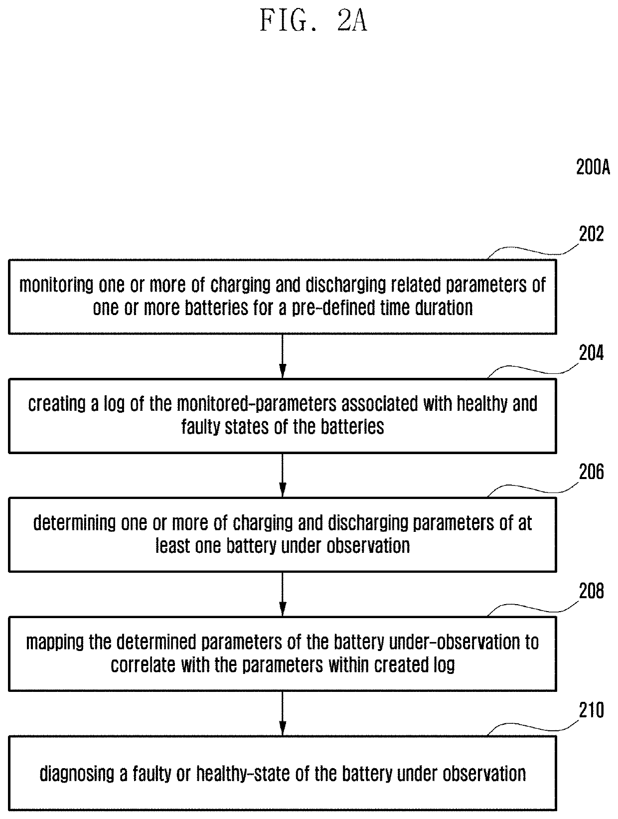
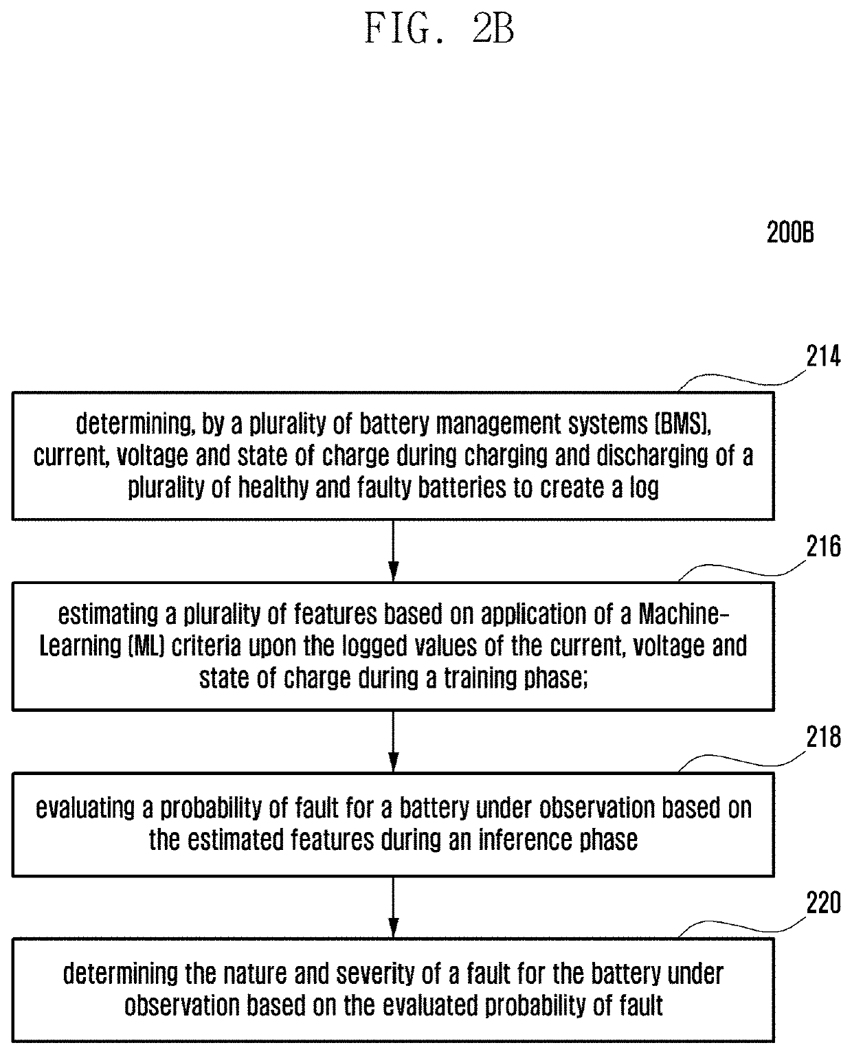
[0011]The present subject matter at-least applies data-driven techniques to the recorded battery current, voltage and SOC data from the BMS to detect different types of battery-faults. The proposed solution also determines the severity of the problem and takes preventive actions depending on the type of the fault and its severity to prevent any hazardous incident and helps ensure user safety. Two different data driven techniques can be applied to solve the fault diagnosis problem. One of them is ML based method and another one is pure statistical likelihood ratio based method. Both the techniques can also be applied together to get more robust fault estimation. The proposed method can detect faults in almost real-time (<1 min), which gives enough lead-time to prevent any subsequent hazardous incidents.

Problems solved by technology

With the advent of technologies, devices and systems are becoming more power hungry, and require high energy density battery.
In addition, the smart devices leave minimum room to accommodate the batteries.
However, any rechargeable battery may become faulty due to various reasons such as over-discharging, over charging, internal short circuit, mechanical abuse, etc.
The faults of such kinds may cause battery swelling, puncture of battery casing, release of hazardous gas and chemicals, thermal runaway, etc. which are all potential threats to the human safety and can also impact the brand equity.
A rechargeable-battery may become faulty due to manufacturing defects or non-standard usages of the device.
For example, a non-standard charging adapter may cause over-charging fault in the battery, mechanical damage of the battery may cause serious physical damage to the battery electrodes and separators.
Such faulty batteries may swell, release harmful chemicals and gas, heat up and undergo thermal runway.
Under such scenarios, most of the battery fault detection algorithms will fail or provide erroneous results.

Method used


Image

  • Method and system for battery-management in devices
  • Method and system for battery-management in devices
  • Method and system for battery-management in devices

Examples


Embodiment Construction

lass="d_n">[0031]FIGS. 1 through 11, discussed below, and the various embodiments used to describe the principles of the present disclosure in this patent document are by way of illustration only and should not be construed in any way to limit the scope of the disclosure. Those skilled in the art will understand that the principles of the present disclosure may be implemented in any suitably arranged system or device.

[0032]For the purpose of promoting an understanding of the principles of this disclosure, reference will now be made to the example embodiments illustrated in the drawings and specific language will be used to describe the same. It will nevertheless be understood that no limitation of the scope of this disclosure is thereby intended, such alterations and further modifications in the illustrated system, and such further applications of the principles of this disclosure as illustrated therein being contemplated as would normally occur to one skilled in the art to which th...


PUM

PropertyMeasurementUnit
currentaaaaaaaaaa
voltageaaaaaaaaaa
probability density functionsaaaaaaaaaa

Abstract

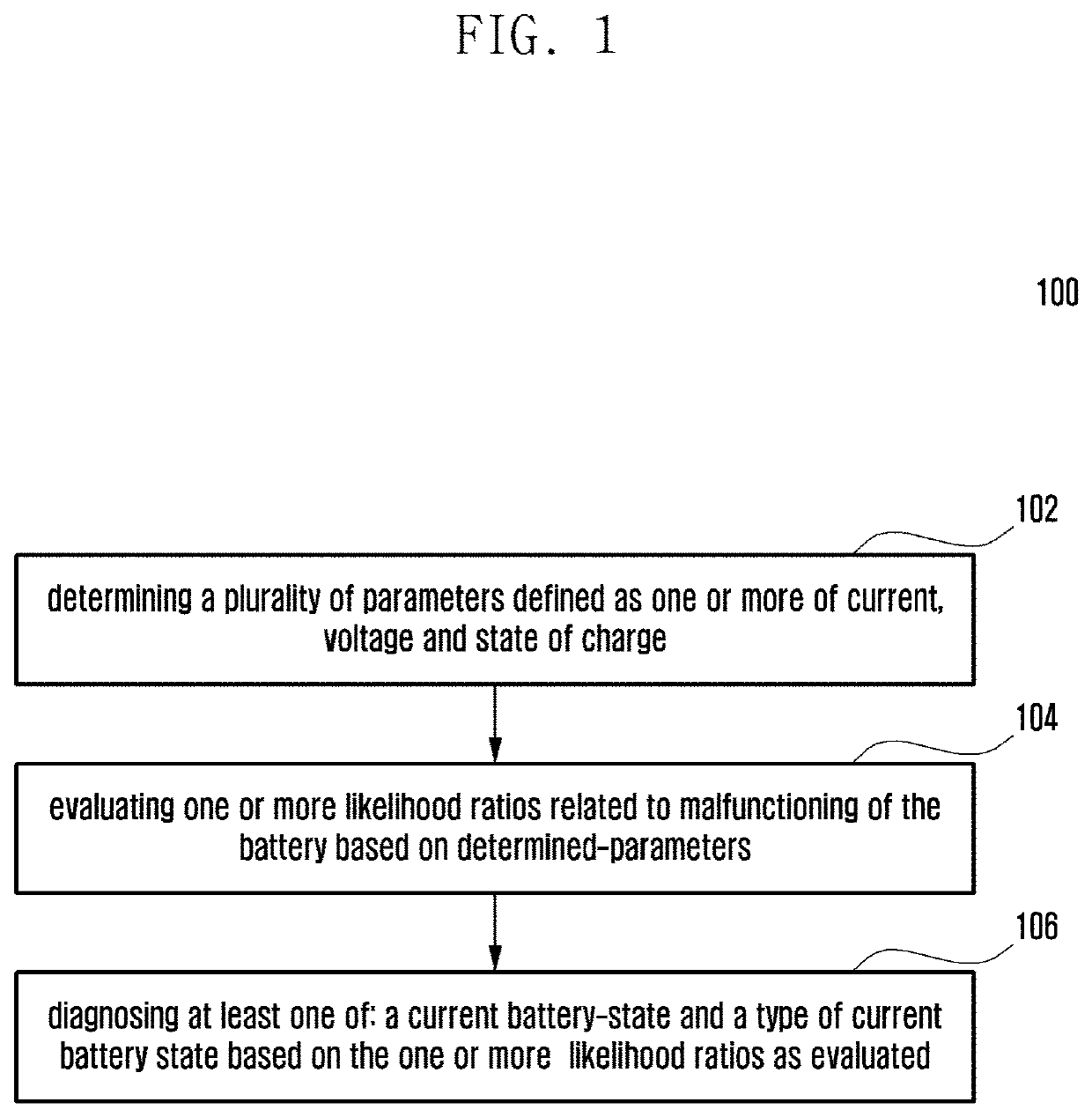
The present subject refers to a method for battery fault diagnosis and prevention of hazardous conditions. The method comprises determining a plurality of parameters defined as one or more of current, voltage, or state of charge during operation of a battery-powered device. Further, one or more likelihood ratios related to malfunctioning of the battery are evaluated based on determined parameters. At least one of: a current battery-state or a type of current battery state are determined based on the one or more likelihood ratios as evaluated.

Description

CROSS-REFERENCE TO RELATED APPLICATIONS[0001]This application is based on and claims priority under 35 U.S.C. § 119 to Indian Provisional Patent Application No. 201941037887 filed on Sep. 19, 2019 and Indian Non-Provisional Patent Application No. 201941037887 filed on Aug. 20, 2020 in the Indian Patent Office, the disclosures of which are herein incorporated by reference in their entirety.BACKGROUND1. Field[0002]The present subject matter relates to battery state monitoring and in particular relates to smart mechanism for fault diagnosis.2. Description of Related Art[0003]With the advent of technologies, devices and systems are becoming more power hungry, and require high energy density battery. In addition, the smart devices leave minimum room to accommodate the batteries. Importantly, appropriate safety measures need to be taken so that hazardless device operation can be achieved. However, any rechargeable battery may become faulty due to various reasons such as over-discharging, ...

Claims


Application Information

Patent Timeline
Patent Type & Authority Applications(United States)
IPC IPC(8): G01R31/367H02J7/00G01R31/392G01R31/3842H01M10/48H01M10/42
CPCG01R31/367H02J7/005G01R31/392H01M2010/4271H01M10/48H01M10/425G01R31/3842G01R31/382G01R31/52Y02E60/10H02J7/0047
Inventor NAHA, ARUNAVAKONETI, ACHYUTHA KRISHNATAGADE, PIYUSHKHANDELWAL, ASHISHHAN, SEONGHOHARIHARAN, KRISHNAN S.
Owner SAMSUNG ELECTRONICS CO LTD
Why Eureka
Try Eureka